Chapter 2
Hardware Overview
2-2
ni.com
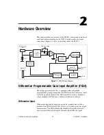
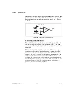
presented at the negative input is subtracted from the signal presented at the
positive input. As shown in Figure 2-2, this subtraction removes ground
noise from the signal. The inner conductor of the BNC is V+. The outer
shell is V–.
Figure 2-2.
Signal Noise-Free Measurements
Grounding Considerations
The path for the positive signal has been optimized for speed and linearity.
You should always apply signals to the positive input and ground to the
negative input. Reversing the inputs results in higher distortion and lower
bandwidth.
The negative input of the amplifier is grounded to PC ground through a
10 k
Ω
resistor. The PGIA is therefore referenced to ground, so it is not
necessary to make any external ground connections. If the device you
connect to the NI 5911 is already connected to ground, ground-loop noise
voltages may be induced into your system. Notice that in most of these
situations, the 10 k
Ω
resistance to PC ground is normally much higher than
the cable impedances you use. As a result, most of the noise voltage occurs
at the negative input of the PGIA where it is rejected, rather than in the
positive input, where it would be amplified.
+
–
V
out
V+
Input Signal
Ground Noise
V–
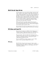
PGIA

