Chapter 3
Signal Connections
©
National Instruments
3-13
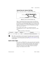
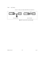
Fig
u
re 3-7 shows the timing req
u
irements for the Ctr
n
A
u
x signal.
Figure 3-7.
Timing Requirements for the CtrnAux Signal
Counter
n
Internal Output Signal
The Co
u
nter
n
Internal O
u
tp
u
t (Ctr
n
InternalO
u
tp
u
t) signal is available only
as an o
u
tp
u
t on the CTR
n
OUT pin, where
n
is the n
u
mber of yo
u
r co
u
nter.
For example, the Ctr0InternalO
u
tp
u
t signal is available as an o
u
tp
u
t on the
PFI 36/CTR 0 OUT pin. Yo
u
can also ro
u
te the Ctr
n
InternalO
u
tp
u
t signal
to other locations on the board, s
u
ch as RTSI.
The Ctr
n
InternalO
u
tp
u
t signal reflects the terminal co
u
nter (TC) of
co
u
nter
n
. The co
u
nter generates a terminal co
u
nt when its co
u
nt val
u
e
rolls over. The two software-selectable o
u
tp
u
t options are p
u
lse on TC and
toggle o
u
tp
u
t polarity on TC. The o
u
tp
u
t polarity is software-selectable
for both options. This o
u
tp
u
t is set to high-impedance at start
u
p.
Hardware Arm Start Triggers
Yo
u
can arm each co
u
nter
u
sing a software command or by
u
sing the
Arm Start Trigger. The Arm Start Trigger may be an internal or an external
signal. By
u
sing the Arm Start Trigger, yo
u
can start more than one co
u
nter
sim
u
ltaneo
u
sly by config
u
ring each co
u
nter to
u
se the same Arm Start
Trigger signal.
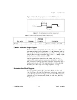
Table 3-7.
Minimum Pulse Width for Ctr
n
Aux Internal Signals
Parameter
Minimum
Minimum
with RTSI
Connector
Description
Ta
u
xpw
5 ns
5 ns
Ctr
n
A
u
x minim
u
m p
u
lse width
Ctr
n
Aux
Tauxpw
Tauxpw
Summary of Contents for PCI-6601
Page 1: ...PCI 6601...

