Chapter 5
Signal Connections
NI PCI-7342 Hardware User Manual
5-12
ni.com
generation. To activate shutdown, the signal must transition from a low
to high state (rising edge). Shutdown occurs when a rising edge is
detected on the shutdown line.
•
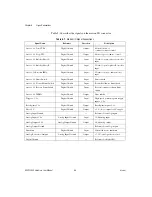
Breakpoint Output <1..2>
—You can program a breakpoint output to
transition when the associated encoder value equals the breakpoint
position. You can use a breakpoint output to directly control actuators
or as a trigger to synchronize data acquisition or other functions in the
motion control system.
You can program breakpoints as either absolute, modulo, or relative
position. You can preset breakpoint outputs to a known state so that
when the breakpoint occurs the transition is low to high, high to low,
or toggled.
Open-collector TTL buffers drive the breakpoint outputs. These
buffers feature 64 mA sink current capability and built-in 3.3 k
Ω
pull-up resistors to +5 V.
You can directly set and reset breakpoint outputs to use as
general-purpose digital outputs.
Wiring Concerns
Caution
Keep trigger input, shutdown input, and breakpoint output signals and their
ground connections wired separately from the motor driver/amplifier signal and encoder
signal connections. Wiring these signals near each other can cause faulty operation.
Excessive input voltages can cause erroneous operation and/or component failure.
Trigger Input, Shutdown Input, and Breakpoint
Output Circuits
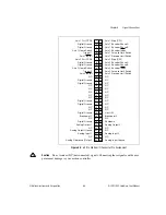
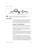
Figures 5-8, 5-9, and 5-10 show a simplified schematic diagram of the
circuits trigger inputs, shutdown inputs, and breakpoint outputs use for
signal buffering.
Figure 5-8.
Trigger Input Circuit
From the External
Connector
Trigger Pins
To the Trigger
Circuits
3.3 k
Ω
DGND
Vcc
74HC244
1 k
Ω
1/8 W


