


Appendix B
Cable Connector Descriptions
NI PCI-7342 Hardware User Manual
B-2
ni.com
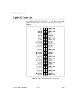
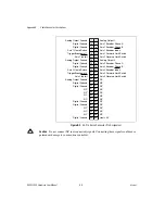
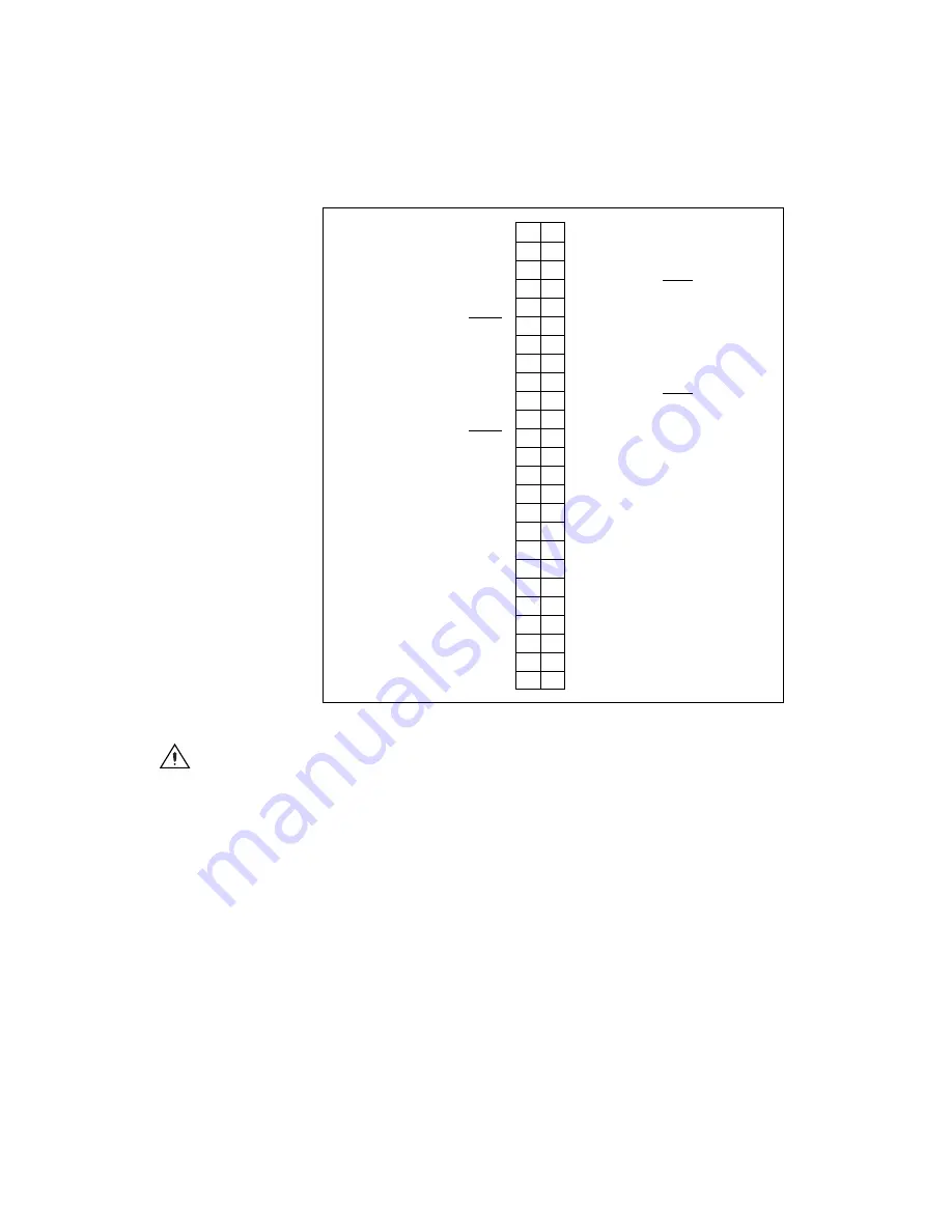
Figure B-2.
50-Pin Servo Connector Pin Assignment
Caution
Do
not
connect NC (not connected) signals. Connecting these signals could cause
permanent damage to your motion controller.
Digital Ground
NC
NC
NC
Digital Ground
Digital Ground
NC
NC
NC
NC
Digital Ground
Digital Ground
Analog Output Ground
Axis 2 Inhibit
Trigger/Breakpoint 2
Axis 2 Home Switch
Digital Ground
Digital Ground
Analog Output Ground
Axis 1 Inhibit
Trigger/Breakpoint 1
Axis 1 Home Switch
Digital Ground
Digital Ground
Analog Output Ground
Host +5 V
NC
NC
NC
NC
NC
NC
NC
NC
NC
NC
NC
NC
Axis 2 Reverse Limit Switch
Axis 2 Forward Limit Switch
Axis 2 Encoder Index
Axis 2 Encoder Phase B
Axis 2 Encoder Phase A
Analog Output 2
Axis 1 Reverse Limit Switch
Axis 1 Forward Limit Switch
Axis 1 Encoder Index
Axis 1 Encoder Phase B
Axis 1 Encoder Phase A
Analog Output 1
49 50
47 48
45 46
43 44
41 42
39 40
37 38
35 36
33 34
31 32
29 30
27 28
25 26
23 24
21 22
19 20
17 18
15 16
13 14
11 12
9
10
7
8
5
6
3
4
1
2


