background image

NI-FBUS Installation Guide for Windows

4

ni.com

PCMCIA-FBUS/2 cable has two connectors. Refer to Chapter 3, 

Connector and Cabling

, of the 

NI-FBUS Hardware and Software User 

Manual

, for more information about these two connectors.

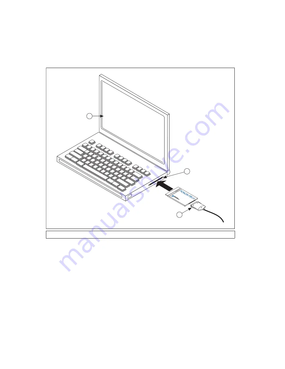
Figure 2.  

Inserting the PCMCIA-FBUS Card

3.

Connect the PCMCIA-FBUS to the Fieldbus network.

Your kit contains a PCMCIA-FBUS cable. Refer to Chapter 3, 

Connector and Cabling

, of the 

NI-FBUS Hardware and Software User 

Manual

, if you need a longer cable than the PCMCIA-FBUS cable 

provided.

1

Port

a

ble Comp

u

ter

2

PCMCIA 

S

ocket

3

PCMCIA-FBU

S

 C

a

ble

1

2

3

Summary of Contents for PCI-FBUS

Page 1: ...BUS HSE H1 LD 7 Installing the Software Complete the following steps to install the NI FBUS software Caution If you are reinstalling the NI FBUS software over a previous version write down your card c...

Page 2: ...ries 2 and PCMCIA FBUS 2 Series 2 Install Your PCI FBUS Card Caution Before you remove the card from the package touch the antistatic plastic package to a metal part of the system chassis to discharge...

Page 3: ...ommunications Manager or NI FBUS Configurator Install Your PCMCIA FBUS Card Caution Before you remove the card from the package touch the antistatic plastic package to a metal part of the system chass...

Page 4: ...e information about these two connectors Figure 2 Inserting the PCMCIA FBUS Card 3 Connect the PCMCIA FBUS to the Fieldbus network Your kit contains a PCMCIA FBUS cable Refer to Chapter 3 Connector an...

Page 5: ...Windows Install Your USB 8486 Caution Operate the USB 8486 only as described in the operating instructions Do not unplug the USB 8486 when the NI FBUS software is running Figure 3 Connecting the USB 8...

Page 6: ...in Figure 3 and Figure 4 3 Connect the USB 8486 to the Fieldbus network Refer to the NI FBUS Hardware and Software User Manual for more information about the connectors 4 Launch the Interface Configur...

Page 7: ...following steps 1 Use a flathead screwdriver to open the DIN rail clip to the unlocked position as shown in Figure 5 Figure 5 DIN Rail Clip 2 Hook the lip on the rear of the FBUS HSE H1 LD onto the t...

Page 8: ...Ethernet hub using a standard Category 5 Ethernet cable Note Do not use a cable longer than 100 m If you are using a 10 Mbps Ethernet National Instruments recommends using a Category 5 shielded twiste...

Page 9: ...ower Connector Pinout 8 Power on your FBUS HSE H1 LD At power up the FBUS HSE H1 LD runs a set of power on self tests POST that take several seconds and the green POWER LED is lit For more information...

Page 10: ...ruments trademarks Other product and company names mentioned herein are trademarks or trade names of their respective companies For patents covering National Instruments products technology refer to t...

Reviews: