background image

Getting Started with R Series Multifunction RIO

6

ni.com

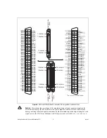
Figure 5.  

NI 783

x

R/784

x

R/785

x

R Connector Pin Assignments and Locations

Caution

Connections that exceed any of the maximum ratings of input or output signals on the 

NI 78

xx

R can damage the NI 78

xx

R device and the computer or chassis. NI is 

not

 liable for any 

damage resulting from such signal connections. For the maximum input and output ratings for each 
signal, refer to the 

NI R Series Multifunction RIO Specifications

, available at 

ni.com/manuals

.

+5V

DGND

DGND

DGND

DGND

DGND

DGND

DGND

DGND

DIO

8

DIO10

DIO12

DIO14

AOGND7

AOGND6

AOGND5

AOGND4

AOGND

3

AOGND2

AOGND1

AOGND0

No Connect

AI7–

1

AIGND7

AI6–

1

AI5–

1

AIGND5

AI4–

1

AI

3

AIGND

3

AI2–

AI1–

AIGND1

AI0–

+5V

DIO1

DIO2

DIO4

DIO5

DIO6

DIO7

DIO0

DIO

3

DIO9

DIO11

DIO1

3

DIO15

AO7

1

AO6

1

AO5

1

AO4

1

AO

3

AO2

AO1

AO0

AI

S

EN

S

E

AI7+

1

AIGND6

AI6+

1

AI5+

1

AIGND4

AI4+

1

AI

3

+

AIGND2

AI2+

AI1+

AIGND0

AI0+

3

5

1

3

6

2

3

7

3

38

4

3

9

5

40

6

41

7

42

8

4

3

9

44 10

45 11

46 12

47 1

3

4

8

14

49 15

50 16

51 17

52 1

8

5

3

19

54 20

55 21

56 22

57 2

3

5

8

24

59 25

60 26

61 27

62 2

8

6

3

29

64

3

0

65

3

1

66

3

2

67

33

6

8 3

4

1

 No Connect on the NI 7

83

0R

DGND

DGND

DGND

DGND

DGND

DGND

DGND

DGND

DGND

DGND

DGND

DGND

DGND

DGND

DGND

DGND

DGND

DGND

DGND

DGND

DGND

DGND

DGND

DGND

DGND

DGND

+5V

+5V

DIO2

8

DIO

3

1

DIO

33

DIO

3

5

DIO

3

7

DIO

3

9

DIO0

DIO2

DIO

3

DIO5

DIO6

DIO7

DIO

8

DIO1

DIO4

DIO9

DIO10

DIO11

DIO12

DIO1

3

DIO14

DIO15

DIO16

DIO17

DIO1

8

DIO19

DIO20

DIO21

DIO22

DIO2

3

DIO24

DIO25

DIO26

DIO27

DIO29

DIO

3

0

DIO

3

2

DIO

3

4

DIO

3

6

DIO

38

3

5

1

3

6

2

3

7

3

38

4

3

9

5

40

6

41

7

42

8

4

3

9

44 10

45 11

46 12

47 1

3

4

8

14

49 15

50 16

51 17

52 1

8

5

3

19

54 20

55 21

56 22

57 2

3

5

8

24

59 25

60 26

61 27

62 2

8

6

3

29

64

3

0

65

3

1

66

3

2

67

33

6

8 3

4

CONNECT

OR 1

(RDIO)

TERMINAL 

3

4

TERMINAL 6

8

TERMINAL 

3

5

TERMINAL 1

TERMINAL 

3

5

TERMINAL 1

TERMINAL 

3

4

TERMINAL 6

8

TERMINAL 

3

4

TERMINAL 6

8

TERMINAL 

3

5

TERMINAL 1

CONNECT

OR 0

(RMIO)

CONNECT

OR 2

(RDIO)

Summary of Contents for PCIe-784 R Series

Page 1: ...Devices NI 78xxR Required Components The following items are necessary to set up and use the NI 78xxR The following software packages LabVIEW LabVIEW FPGA Module NI RIO device drivers Optional LabVIEW...

Page 2: ...uctions for the NI RIO driver The listed documents are available at ni com manuals In LabVIEW 8 0 or later you can also view the LabVIEW Manuals directory that contains these documents by selecting St...

Page 3: ...irst Safety and Electromagnetic Compatibility document packaged with your PXI chassis or device before removing equipment covers or connecting or disconnecting any signal wires 2 Remove the computer c...

Page 4: ...R replace the computer cover if applicable 7 Plug in and power on the computer or PXI chassis To confirm that your device is recognized complete the following additional steps 1 Select Start All Progr...

Page 5: ...D DGND DGND DGND 5V 5V DIO28 DIO31 DIO33 DIO35 DIO37 DIO39 DIO0 DIO2 DIO3 DIO5 DIO6 DIO7 DIO8 DIO1 DIO4 DIO9 DIO10 DIO11 DIO12 DIO13 DIO14 DIO15 DIO16 DIO17 DIO18 DIO19 DIO20 DIO21 DIO22 DIO23 DIO24 D...

Page 6: ...1 AI5 1 AIGND4 AI4 1 AI3 AIGND2 AI2 AI1 AIGND0 AI0 35 1 36 2 37 3 38 4 39 5 40 6 41 7 42 8 43 9 44 10 45 11 46 12 47 13 48 14 49 15 50 16 51 17 52 18 53 19 54 20 55 21 56 22 57 23 58 24 59 25 60 26 6...

Page 7: ...available at ni com manuals Table 1 R Series Connectivity Options Cable Connector Accessory Description NI 781xR NI 783xR 784xR 785xR SHC68 68 RMIO NI Recommended 0 NI SCB 68 High performance shielde...

Page 8: ...projects designed to help you get started using your R Series device 4 Select Basic I O and then select Analog Input R Series lvproj 5 The Analog Input example project opens in the Project Explorer w...

Page 9: ...earlier do not use the Configure Open FPGA VI Reference dialog to update the FPGA target in the host VI For LabVIEW version 8 5 1 and earlier right click the Open FPGA VI Reference function on the bl...

Page 10: ...om the shortcut menu as shown in the following figure 2 In the Project Explorer window right click the FPGA target and select New FPGA I O 3 In the New FPGA I O dialog box expand Connector0 and select...

Page 11: ...from the FPGA Interface palette between the Invoke method and the Read Write Control that already exists on the block diagram c Wire the FPGA VI Reference Out terminal of the Invoke Method node to th...

Page 12: ...channel 0 Where to Go From Here The following resources contain information for writing applications and taking measurements with R Series Multifunction RIO devices Software Documentation LabVIEW FPGA...

Page 13: ...the LabVIEW FPGA platform To access the LabVIEW FPGA IPNet visit ni com ipnet Where to Go for Support The National Instruments Web site is your complete resource for technical support At ni com suppo...

Page 14: ...er product and company names mentioned herein are trademarks or trade names of their respective companies For patents covering National Instruments products technology refer to the appropriate locatio...

Reviews: