Quick Start Guide
Phase Matrix PXI-1430B RF Downconverter Module
29
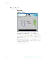
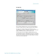
PXI-1430 Corrections
The following corrections were made to adjust the level of
IF attenuation so that no part of the IF chain is overloaded for the given
RF B IN Frequency. The values displayed here for IF ATTEN 1,
IF ATTEN 2, and IF Fine Loss can be used to accurately set the system
gain to 38 dB for a given RF B IN Frequency. Using this Soft Front
Panel, the user can only change the RF B IN Frequency and view
calibration data associated with that frequency. This Soft Front Panel
cannot be used to change the actual value of IF ATTEN 1, IF ATTEN 2,
or IF Fine; it is only used to view the values that should be set in order to
obtain a system gain of 38 dB. This value can be set from the
Control Tab.
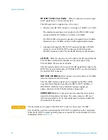
IF ATTEN 1
represents the setting of IF ATTEN 1 for a particular
RF B IN frequency. This represents the correction value that needs to be
set for IF ATTEN 1 of the unit. This value can be set from the
Control Tab.
IF ATTEN 2
represents the setting of IF ATTEN 2 for a particular
RF B IN frequency. This represents the correction value that needs to be
set for IF ATTEN 2 of the unit. This value can be set from the
Control Tab.
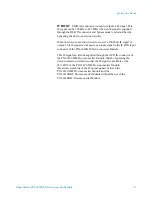
IF Fine Loss
represents a residual error that exists after setting
IF ATTEN 1 and IF ATTEN 2. This error cannot be corrected in the
PXI module due to the 0.5 dB step limitation of IF ATTEN 1 and
IF ATTEN 2. This residual error value cannot be set from the Control
tab or this Cal Data tab, it can only be mathematically applied
externally.
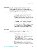
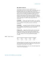
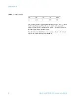
The Bypass Response table displays bypass port response data stored in
the PXI-1430B’s memory during each measurement. These data values
are displayed as port response over frequency.
Use the Horizontal Slider Bar to view values to the left and right of the
values currently being displayed.
Table 3
Bypass Response
230
240
250
260
MHz
-2.02
-2.05
-2.06
-2.09
dB


