Chapter 2
Installation, Configuration, and Operation
2-4
©
National Instruments Corporation
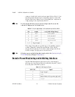
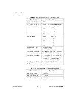
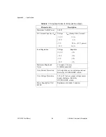
connector (9-pin D-sub) located on the rear panel. Refer to Table 2-2 for a
pinout diagram of the remote power monitoring connector. Connect the
reference lead of the voltmeter to one of the ground pins. Compare each
voltage reading to the values listed in Table 2-1.
Note
Use the rear-panel D-sub connector to check voltages only. Do not use the
connector to supply power to external devices.
If the voltages fall within the specified ranges, the mainframe complies
with the CompactPCI voltage limit specifications. Notice that the
rear-panel D-sub connector is to be used to check voltages only. Do not
use these voltages to supply power to external devices.
Note
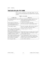
If the fans or power unit fail to function properly, refer to the
section of Chapter 3,
.
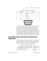
Remote Power Monitoring and Inhibiting Interface
The PXI-1000B mainframe supports remote power monitoring and
inhibiting via a 9-pin D-sub connector located on the rear panel. Table 2-2
shows the pinout of the DB-9 connector.
Table 2-1.
Power Supply Voltages at Power Monitoring Connector (DB-9)
Pin
Supply
Acceptable Voltage Range
2
+5 V
4.75 to 5.25 V
4
+3.3 V
3.135 to 3.465 V
6
+12 V
11.4 to 12.6 V
8
–12 V
–12.6 to –11.4 V
1, 9
Logic Ground
N/A
Table 2-2.
DB-9 Connector Pinout
DB-9 Pin
Signal
1
Logic Ground
2
+5 V
3
Inhibit Return (DC-capable supply only)
4
+3.3 V

