Chapter 2
Installation, Configuration, and Operation
©
National Instruments Corporation
2-5
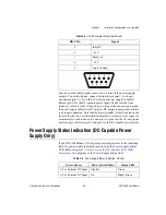
You can use the Inhibit signal (active low) to turn off the power supply
outputs. To use this feature, connect the Inhibit pin (pin 5) to a Logic
Ground pin (pin 1 or 9) on the AC-only input power supply or Inhibit
Return (pin 3) for the DC-capable power supply. Make sure the front
(standby) switch is in the ON position. As long as the connection is made,
the power supply inhibits its DC outputs. DC output resumes when Inhibit
is no longer connected. Note that the power (standby) switch, located on the
front of the chassis, uses this inhibiting feature. For remote reset, connect a
momentary switch between pin 5 and pin 1 (or pin 9) on the AC-only input
power supply or between pin 5 and pin 3 for the DC-capable power supply.
Power Supply Status Indication (DC-Capable Power
Supply Only)
If your PXI-1000B has a DC-capable power supply refer to the following
table for power supply indications provided by the Power Supply Status
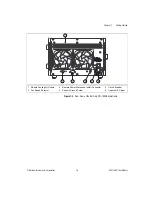
LED. Refer to Figure 1-3,
Rear View of the DC-Capable PXI-1000B
, for a diagram of the Power Supply Status LED.
.
5
Inhibit*
6
+12 V
7
Reserved
8
–12 V
9
Logic Ground
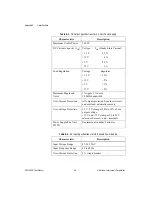
Table 2-3.
Power Supply Status Indication, DC Only
Power Source
Power Switch Mode
Status LED
AC or External DC Input
Standby
Green
AC or External DC Input
On
Bright Green
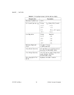
Table 2-2.
DB-9 Connector Pinout (Continued)
DB-9 Pin
Signal
5
4
3
2
1
9
8
7
6

