


Contents
©
National Instruments Corporation
vii
NI PXI-1010 Chassis User Manual
Figures
Figure 1-1.
The Relationship among the Programming Environment,
NI-DAQ, and Your Hardware ...............................................................1-4
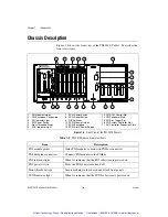
Figure 1-2.
Front View of the PXI-1010 Chassis ....................................................1-6
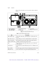
Figure 1-3.
Rear View of the PXI-1010 Chassis......................................................1-8
Figure 1-4.
PXI Star Trigger and Local Bus Routing ..............................................1-11
Figure 2-1.
Address Setting Examples.....................................................................2-2
Figure 2-2.
Installing PXI or CompactPCI Modules (PXI Module Shown)............2-5
Figure 2-3.
Injector/Ejector Handle Position during Module Insertion ...................2-6
Figure A-1.
PXI-1010 Dimensions (Front View Shown) .........................................A-8
Figure A-2.
PXI-1010 Dimensions (Rear View Shown) ..........................................A-8
Figure A-3.
PXI-1010 Dimensions (Top View Shown) ...........................................A-9
Tables
Table 1-1.
Power Cables .........................................................................................1-2
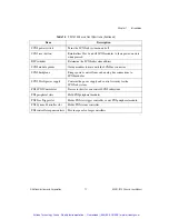
Table 1-2.
PXI-1010 Chassis Front View Items.....................................................1-6
Table 1-3.
PXI-1010 Chassis Rear View Items ......................................................1-8
Table 2-1.
PXI-1010 Voltage Selection and Fuse Ratings by Region....................2-3
Table 2-2.
PXI-1010 Fuse Part Numbers................................................................2-3
Table 3-1.
Troubleshooting Power Failure .............................................................3-5
Table B-1.
P1 (J1) Connector Pin Assignments for the System Controller Slot.....B-2
Table B-2.
P2 (J2) Connector Pin Assignments for the System Controller Slot.....B-3
Table B-3.
P1 (J1) Connector Pin Assignments for the Star Trigger Slot ..............B-4
Table B-4.
P2 (J2) Connector Pin Assignments for the Star Trigger Slot ..............B-5
Table B-5.
P1 (J1) Connector Pin Assignments for the Peripheral Slot .................B-6
Table B-6.
P2 (J2) Connector Pin Assignments for the Peripheral Slot .................B-7
Artisan Technology Group - Quality Instrumentation ... Guaranteed | (888) 88-SOURCE | www.artisantg.com