Chapter 1 Introduction
)
b d
c,c,, pcn)c)c
c
0 0 . 2
( ' - ' " = j " & 7 '
S
e
e
r
y
e
' ' ' C ' e '
,,,,coov 00000,,,,,
- 6 0 0 0 , 1 0 0 0 G - 0 0 0 0 0
i
O
0'D"
[]
-
,4,f0,i,c,00co.t)eeeeeooeoeoo
m n M . M I M r ( r ( M o Tr
- . ; : i ) : i c ; r j r ) O C ( 0 0 0 . 0 0 0 0 0 0 0 0 0 0 0 0
(c--
9
0
- -
--__
X ,
/
0 9 0
7 '
/
(
0
1
- - - - /
0
0
®
0
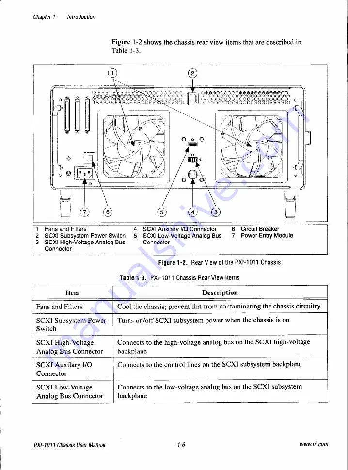
1 F a n s and Filters
4
S C X I Auxilary I/O Connector
6
Circuit Breaker
2 S C X I Subsystem Power Switch 5 S C X I Low-Voltage Analog Bus 7 P o w e r Entry Module
3 S C X I High-Voltage Analog Bus C o n n e c t o r
Connector
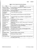
Item
Description
Fans and Filters
Cool the chassis; prevent dirt from contaminating the chassis circuitry
SCXI Subsystem Power
Switch
Turns on/off SCXI subsystem power when the chassis is on
SCXI High-Voltage
Analog Bus Connector
Connects to the high-voltage analog bus on the SCXI high-voltage
backplane
SCXI Auxilary
I/O
Connector
Connects to the control lines on the SCXI subsystem backplane
SCXI Low-Voltage
Analog Bus Connector
Connects to the low-voltage analog bus on the SCXI subsystem
backplane
Figure 1-2 shows the chassis rear view items that are described in
Table 1-3.
Figure 1-2.
Rear View of the PXI-1011 Chassis
Table 1-3.
PXI-1011 Chassis Rear View Items
PXI-1011 Chassis User Manual
1-6
wwwni.com

