background image

©

 National Instruments Corporation

3-1

PXI-1025 MegaPAC User Manual

3

Maintenance

This chapter describes basic maintenance procedures you can perform 
on the PXI-1025 MegaPAC chassis.

Service Interval

Clean the chassis fan filter at a maximum interval of six months. 
Depending on the amount of use and ambient dust levels in the operating 
environment, the filter may require more frequent cleaning.

Clean dust from the chassis exterior (and interior) as needed, based on 
the operating environment. Periodic cleaning increases reliability.

Preparation

The information in this section is designed for use by qualified service 
personnel. Read the 

For Your Safety

 section at the beginning of this manual 

before attempting any procedures in this chapter.

Caution

Many components within the chassis are susceptible to static discharge damage. 

Service the chassis only in a static-free environment. Observe standard handling 
precautions for static-sensitive devices while servicing the chassis. Always wear 
a grounded wrist strap, or equivalent, while servicing the chassis.

Cleaning

Cleaning procedures consist of exterior and interior cleaning of the chassis 
and cleaning the fan filter. Refer to your module user documentation for 
information on cleaning the individual CompactPCI or PXI modules.

Caution

Always power-off the chassis and disconnect the power cord before cleaning or 

servicing the chassis.

Summary of Contents for PXI-1025 MegaPAC

Page 1: ...PXI PXI 1025 MegaPAC User Manual PXI 1025 MegaPAC User Manual July 2000 Edition Part Number 322532B 01...

Page 2: ...many 089 741 31 30 Greece 30 1 42 96 427 Hong Kong 2645 3186 India 91805275406 Israel 03 6120092 Italy 02 413091 Japan 03 5472 2970 Korea 02 596 7456 Mexico D F 5 280 7625 Mexico Monterrey 8 357 7695...

Page 3: ...unctions or service failures caused by owner s failure to follow the National Instruments installation operation or maintenance instructions owner s modification of the product owner s abuse misuse or...

Page 4: ...interference to radio and television reception Classification requirements are the same for the Federal Communications Commission FCC and the Canadian Department of Communications DOC Changes or modif...

Page 5: ...s Cet appareil num rique de la classe B respecte toutes les exigences du R glement sur le mat riel brouilleur du Canada European Union Compliance to EEC Directives Readers in the EU EEC EEA must refer...

Page 6: ...MegaPAC Adjustments and service to internal components must be undertaken by qualified service technicians During service of this product the mains connector to the premise wiring must be disconnected...

Page 7: ...y with CompactPCI 1 4 System Controller Slot 1 4 Star Trigger Slot 1 4 Peripheral Slots 1 4 Local Bus 1 4 Trigger Bus 1 5 System Reference Clock 1 6 Chapter 2 Installation Configuration and Operation...

Page 8: ...ew 2 2 Figure 2 2 Using the Handle for Bench Top Applications 2 3 Figure 2 3 Installing PXI or CompactPCI Modules 2 6 Figure 2 4 Injector Ejector Handle Position during Module Insertion 2 6 Figure A 1...

Page 9: ...tion to a key concept This font also denotes text that is a placeholder for a word or value that you must supply monospace Text in this font denotes text or characters that you should enter from the k...

Page 10: ...file a claim with the carrier Retain the packing material for possible inspection and or reshipment What You Need to Get Started The PXI 1025 MegaPAC kit contains the following items PXI 1025 MegaPAC...

Page 11: ...mplies with the PXI Specification Revision 1 0 offering advanced timing and synchronization features The key features of the PXI 1025 MegaPAC include PXI and CompactPCI PICMG 2 0 R 2 1 module compatib...

Page 12: ...Video Display 2 CD ROM 3 Display Brightness Control 4 Status LED Indicators 5 Pointing Device 6 Fold Down Keyboard 7 Right Mouse Button 8 Left Mouse Button 1 Power Supply Air Outlet 2 Universal AC In...

Page 13: ...PAC System Controller Slot The System Controller slot is Slot 1 of the chassis as defined by the PXI specification It has three controller expansion slots which are used for system controller modules...

Page 14: ...y This method is a flexible way to define local bus functionality that is not limited by hardware keying Figure 1 3 PXI Local Bus and Star Trigger Routing Trigger Bus The eight PXI trigger lines are b...

Page 15: ...f less than 1 ns between slots drives the clock signal to each peripheral slot You can use this common reference clock signal to synchronize multiple modules in a measurement or control system You can...

Page 16: ...or in an instrument rack Determine how you want to use your PXI 1025 MegaPAC and follow the appropriate installation instructions To facilitate power supply and module cooling air enters through filte...

Page 17: ...er 2 Installation Configuration and Operation PXI 1025 MegaPAC User Manual 2 2 www ni com Figure 2 1 PXI 1025 MegaPAC Chassis Airflow Side View 1 Module Cooling Air Outlets 2 Module Cooling Air Intake...

Page 18: ...Handle for Bench Top Applications Fold Down Keyboard The removable fold down keyboard is shown in Figure 1 1 Front View of the PXI 1025 MegaPAC Chassis The fold down keyboard incorporates a pointing d...

Page 19: ...IGH for maximum cooling or AUTO to employ the temperature sensing module that controls the fan speed Connecting Safety Ground Warning The PXI 1025 MegaPAC chassis is designed with a three position NEM...

Page 20: ...irst placing the module s card edges into the front module guides top and bottom as shown in Figure 2 3 Slide the module into the chassis making sure that the injector ejector handle is pushed down as...

Page 21: ...er Manual 2 6 www ni com Figure 2 3 Installing PXI or CompactPCI Modules Figure 2 4 Injector Ejector Handle Position during Module Insertion 1 PXI 1025 MegaPAC Chassis 2 PXI 8156B System Controller 3...

Page 22: ...e by qualified service personnel Read the For Your Safety section at the beginning of this manual before attempting any procedures in this chapter Caution Many components within the chassis are suscep...

Page 23: ...of the chassis To clean the LCD display wipe with lens paper or optical cloth Cautions Avoid getting moisture inside the chassis during exterior cleaning Use just enough moisture to dampen the cloth...

Page 24: ...C Input frequency range 50 to 60 Hz Power disconnect The power switch causes the power module to supply DC power to the CompactPCI PXI backplane The power cord provides main power disconnect Efficienc...

Page 25: ...1 CSA 22 2 No 1010 1 Installation Category II Pollution Degree 2 Safety Class 1 Environmental Operating temperature 0 to 50 C Storage temperature 20 to 70 C Operating relative humidity 10 to 90 noncon...

Page 26: ...nsion slots and seven peripheral slots Compliant with IEEE 1101 10 mechanical packaging PXI Specification Revision 1 0 Compliant Accepts both PXI and CompactPCI PICMG 2 0 R2 1 3U modules Backplane bar...

Page 27: ...pendix A Specifications PXI 1025 MegaPAC User Manual A 4 www ni com Figure A 1 shows the PXI 1025 MegaPAC dimensions Figure A 1 PXI 1025 MegaPAC Dimensions 841 in 2136 cm 1625 in 4127 cm 1825 in 4635...

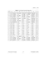
Page 28: ...or the System Controller slot Table B 2 shows the P2 J2 connector pinout for the System Controller slot Table B 3 shows the P1 J1 connector pinout for the Star Trigger slot Table B 4 shows the P2 J2 c...

Page 29: ...AD 14 GND AD 13 GND 18 GND SERR GND 3 3 V PAR C BE 1 GND 17 GND 3 3 V SDONE SBO GND PERR GND 16 GND DEVSEL GND V I O STOP LOCK GND 15 GND 3 3 V FRAME IRDY GND TRDY GND 12 14 Key Area 11 GND AD 18 AD...

Page 30: ...GND PXI_TRIG1 PXI_TRIG0 DEG GND PXI_TRIG7 GND 15 GND PXI_BRSVA15 GND FAL REQ5 GNT5 GND 14 GND AD 35 AD 34 AD 33 GND AD 32 GND 13 GND AD 38 GND V I O AD 37 AD 36 GND 12 GND AD 42 AD 41 AD 40 GND AD 39...

Page 31: ...14 GND AD 13 GND 18 GND SERR GND 3 3 V PAR C BE 1 GND 17 GND 3 3 V SDONE SBO GND PERR GND 16 GND DEVSEL GND V I O STOP LOCK GND 15 GND 3 3 V FRAME IRDY GND TRDY GND 12 14 Key Area 11 GND AD 18 AD 17...

Page 32: ...16 GND PXI_TRIG1 PXI_TRIG0 DEG GND PXI_TRIG7 GND 15 GND PXI_BRSVA15 GND FAL PXI_STAR6 PXI_LBR6 GND 14 GND AD 35 AD 34 AD 33 GND AD 32 GND 13 GND AD 38 GND V I O AD 37 AD 36 GND 12 GND AD 42 AD 41 AD 4...

Page 33: ...14 GND AD 13 GND 18 GND SERR GND 3 3 V PAR C BE 1 GND 17 GND 3 3 V SDONE SBO GND PERR GND 16 GND DEVSEL GND V I O STOP LOCK GND 15 GND 3 3 V FRAME IRDY GND TRDY GND 12 14 Key Area 11 GND AD 18 AD 17 A...

Page 34: ...GND PXI_TRIG1 PXI_TRIG0 DEG GND PXI_TRIG7 GND 15 GND PXI_BRSVA15 GND FAL PXI_LBL6 PXI_LBR6 GND 14 GND AD 35 AD 34 AD 33 GND AD 32 GND 13 GND AD 38 GND V I O AD 37 AD 36 GND 12 GND AD 42 AD 41 AD 40 G...

Page 35: ...the latest example programs system configurators tutorials technical news as well as a community of developers ready to share their own techniques Customer Education National Instruments provides a n...

Page 36: ...b sites from the Worldwide Offices section of www ni com Branch office web sites provide up to date contact information support phone numbers e mail addresses and current events If you have searched t...

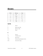
Page 37: ...Prefix Meaning Value n nano 10 9 micro 10 6 m milli 10 3 c centi 10 2 k kilo 103 M mega 106 Symbols Degrees Equal or greater than Equal or less than Percent A A Amperes AC Alternating current Ah Ampe...

Page 38: ...rch CSA Canadian Standards Association D daisy chain A method of propagating signals along a bus in which the devices are prioritized on the basis of their position on the bus DC Direct current E ECL...

Page 39: ...es per second I IEC International Electrotechnical Commission an organization that sets international electrical and electronics standards IEEE Institute of Electrical and Electronics Engineers IMP Ma...

Page 40: ...unctionality that can provide individual triggers to all other peripherals System controller A module configured for installation in Slot 1 of a PXI chassis This device is unique in the PXI system in...

Page 41: ...2 setting fan speed 2 4 Customer Education C 1 D dimensions figure A 4 documentation conventions used in manual ix related documentation ix F fan setting speed 2 4 fan filter cleaning 3 2 fold down ke...

Page 42: ...1 connector pinouts table B 6 P2 J2 connector pinouts table B 7 pinouts B 1 P1 J1 connector peripheral slot table B 6 Star Trigger slot table B 4 system controller slot table B 2 P2 J2 connector perip...

Page 43: ...A 4 backplane A 3 cooling A 2 dimensions figure A 4 electrical A 1 environmental A 2 mechanical A 3 safety A 2 Star Trigger ST slot description 1 4 P1 J1 connector pinouts table B 4 P2 J2 connector p...

Reviews: