Chapter 1
Getting Started
©
National Instruments Corporation
1-7
NI PXI-1036/PXI-1036DC User Manual
System Controller Slot
The system controller slot is slot 1 of the chassis as defined by the PXI
specification. It has one controller expansion slot for system controller
modules that are wider than one slot. As defined in the PXI specification,
these slots allow the controller to expand to the left to prevent the controller
from using peripheral slots.
Star Trigger Slot
The star trigger (ST) slot is slot 2. This slot has dedicated equal-length
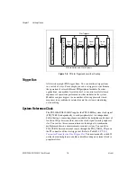
trigger lines between slot 2 and peripheral slots 3 through 6 (refer to
Figure 1-5). Slot 2 is intended for modules with ST functionality that can
provide individual triggers to all other peripheral modules. However, if you
do not require advanced trigger functionality, you can install any standard
peripheral module in this slot.
The star trigger slot can also be used to provide a PXI_CLK10 signal to
the backplane. For more information regarding PXI_CLK10, refer to the
section.
Peripheral Slots
There are five peripheral slots, including the star trigger slot.
Local Bus
The PXI backplane local bus is a daisy-chained bus that connects each
peripheral slot with adjacent peripheral slots to the left and right (refer to
Figure 1-5). For example, the right local bus of slot 2 connects to the left
local bus of slot 3, and so on.
The left local bus signal lines on slot 2 are used for star trigger and do not
connect to slot 1. The right local bus signal lines on slot 6 are not routed
anywhere.
Each local bus is 13 lines wide and can pass analog signals up to
42 V between cards or provide a high-speed TTL side-band digital
communication path that does not reduce the PXI bus bandwidth.
Initialization software uses the configuration information specific to
adjacent peripheral modules to evaluate local bus compatibility.


