Chapter 2
Installation and Configuration
©
National Instruments Corporation
2-5
NI PXI-1036/PXI-1036DC User Manual
Connecting to an AC Power Source
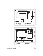
Attach input power through the rear AC inlet using the appropriate
AC power cable supplied. Refer to Figure 1-2,
Rear View of the PXI-1036DC Chassis
the AC inlet.
The power switch allows you to power on the chassis or place it in standby
mode. Press the power switch to the On position (if not already on).
Observe that all fans become operational.
Connecting to a DC Power Source (PXI-1036DC Only)
For full chassis power, the DC source must be capable of providing
a minimum of 300 watts of continuous power per feed pair to the
P1 connector on the PXI-1036DC power supply.
DC Connector
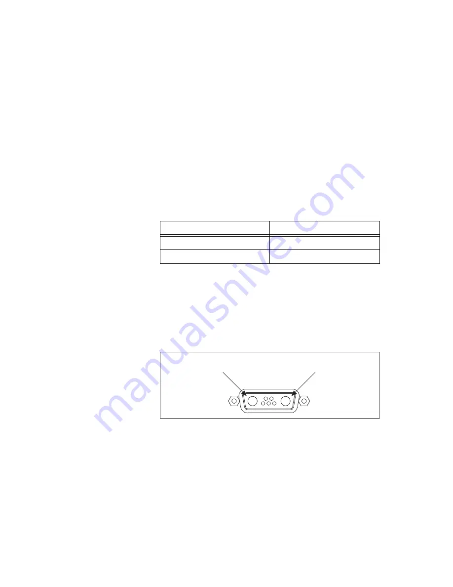
Figure 2-2 shows the DC connector (P1) that appears on the rear panel of
the PXI-1036DC power supply.
Figure 2-2.
The P1 DC Input Connector
To build a custom DC cable, be sure to note the positive (+) and negative (–)
terminals shown in Figure 2-2. Use the following components or their
equivalents to mate to the P1 port:
•
Positronic connector, part number CBD7W2F0000
•
Positronic hood, part number D15000GE0
Table 2-1.
DC Power Requirements
Electrical Element
Requirement
Voltage
18–30 VDC
DC Input Current
30–10 A
P1
Po
s
itive
(+)
Neg
a
tive
(–)

