Chapter 2
Installation and Configuration
NI PXI-1036/PXI-1036DC User Manual
2-6
ni.com
•
Two Positronic contacts, part number FS4008D (choice of solder cup
or crimp terminals)
•
Use of UL listed AWG #10 wire is recommended
(maximum length: 216 in.)
Install an F30A 500 VDC/600 VAC, 1.5 in.
×
.41 in. (10 mm
×
38 mm)
Midget fast-acting fuse on the positive (+) wire of the custom cable as close
to the power source as practical.
•
A Ferraz-Shawmut FEB-81-81 fuse holder, with
Ferraz-Shawmut FSB1 insulating boots, and an ATM30 fuse
is recommended.
Refer to the
NI PXI-1036DC DC Cable Kit Installation Guide
for
information on fuse installation.
Note
You can purchase an optional DC cable from National Instruments that incorporates
an in-line fuse and the mating connector for the P1 port.
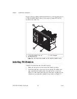
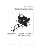
Installing a PXI Controller
This section contains general instructions for installing a PXI controller
in the chassis. Refer to your PXI controller user manual for specific
instructions and cautions. Complete the following steps to install a
controller.
1.
Connect the AC or DC power source to the PXI chassis before
installing the controller. The AC power cord grounds the chassis and
protects it from electrical damage while you install the controller. For
DC powered applications, make sure the chassis is properly grounded
through the chassis ground screw. Make sure the chassis power switch
is in the Off (Standby) position.
Caution
To protect both yourself and the chassis from electrical hazards, leave the chassis
off until you finish installing the controller.

