background image

©

 National Instruments

5-1

NI PXI-8109 User Manual

5

Troubleshooting

This chapter answers common troubleshooting questions you may have 
when using the NI PXI-8109 embedded computer.

What if the NI PXI-8109 does not boot?

Several problems can cause a controller not to boot. Here are some things 
to look for and possible solutions.

Things to Notice

:

Which LEDs come on? The 

PWROK/FAULT

 LED should stay lit 

green. The

Drive

 LED should blink during boot as the disk is 

accessed.

What appears on the display? Does it hang at some particular point 
(BIOS, Operating System, and so on)? If nothing appears on the 
screen, try a different monitor. Does your monitor work with a 
different PC? If it hangs, note the last screen output that you saw for 
reference when consulting National Instruments technical support.

What has changed about the system? Did you recently move the 
system? Was there electrical storm activity? Did you recently add 
a new module, memory chip, or piece of software?

Refer to your chassis user manual for additional troubleshooting steps.

Things to Try

:

Make sure the chassis is plugged in to a working power source. 

Check any fuses or circuit breakers in the chassis or other power 
supply (possibly a UPS).

Make sure the controller module is firmly seated in the chassis.

Remove all other modules from the chassis.

Remove any nonessential cables or devices.

Try the controller in a different chassis.

Try a similar controller in this same chassis.

Clear the CMOS. (Refer to the 

System CMOS

 section of Chapter 2, 

Installation and Configuration

.)

Summary of Contents for PXI-8109

Page 1: ...PXI 8221...

Page 2: ...PXI NI PXI 8109 User Manual NI PXI 8109 User Manual July 2012 373172C 01...

Page 3: ...and current events National Instruments Corporate Headquarters 11500 North Mopac Expressway Austin Texas 78759 3504 USA Tel 512 683 0100 For further support information refer to the Technical Support...

Page 4: ...Under the copyright laws this publication may not be reproduced or transmitted in any form electronic or mechanical including photocopying recording storing in an information retrieval system or trans...

Page 5: ...Y OR DEATH THE USER OR APPLICATION DESIGNER MUST TAKE REASONABLY PRUDENT STEPS TO PROTECT AGAINST SYSTEM FAILURES INCLUDING BUT NOT LIMITED TO BACK UP OR SHUT DOWN MECHANISMS BECAUSE EACH END USER SYS...

Page 6: ...interference will not occur in a particular installation when the product is connected to a test object or if the product is used in residential areas To minimize the potential for the product to cau...

Page 7: ...BIOS Setup 2 5 Accessing BIOS Setup 2 5 Main Menu 2 6 Advanced Menu 2 6 SATA Configuration Submenu 2 7 CPU Configuration Submenu 2 8 Video Configuration Submenu 2 9 Clock Generator Configuration Subm...

Page 8: ...and Software 2 22 Files and Directories Installed on Your Hard Drive 2 22 PXI Features 2 23 PXI Trigger Connectivity 2 23 PXI Chassis Configuration 2 23 Basic PXI System Configuration 2 24 Upgrading R...

Page 9: ...ation Questions General Questions 4 1 Boot Options 4 1 Cables and Connections 4 2 Software Driver Installation 4 3 Upgrade Information 4 4 PXI Configuration 4 7 Chapter 5 Troubleshooting Appendix A Sp...

Page 10: ...through nested menu items and dialog box options to a final action The sequence Options Settings General directs you to pull down the Options menu select the Settings item and select General from the...

Page 11: ...ments contain information you may find helpful as you read this manual PICMG 2 0 R3 0 CompactPCI Specification PCI Industrial Computers Manufacturers Group IEEE Standard P1284 1 1997 C MM Standard for...

Page 12: ...the CompactPCI specification which defines a rugged form factor for PCI that offers superior mechanical integrity and easy installation and removal of hardware components PXI products offer higher an...

Page 13: ...deo one RS 232 serial port a parallel port four high speed USB 2 0 ports a PCI based GPIB controller two Gigabit Ethernet connectors a reset button and PXI triggers The NI PXI 8109 has a dual core Int...

Page 14: ...o PXI Trigger provides a routable connection of the PXI triggers to from the SMB on the front panel The ATI Radeon E2400 Embedded GPU drives the graphics The Watchdog Timer block consists of a watchdo...

Page 15: ...4 slot accommodates an ExpressCard 34 module National Instruments Software National Instruments has developed several software tools you can use with the NI PXI 8109 National Instruments hardware and...

Page 16: ...ut A D conversion buffered data acquisition high speed A D conversion analog output D A conversion waveform generation digital I O counter timer operations SCXI signal conditioning RTSI or PXI synchro...

Page 17: ...For information on writing your own PXI instrument driver with NI VISA refer to the NI VISA Getting Started Manual and the readme txt file in the NI VISA directory For more information visit ni com v...

Page 18: ...Plug in your chassis before installing the NI PXI 8109 The power cord grounds the chassis and protects it from electrical damage while you install the module Make sure the power switch is turned off...

Page 19: ...osition Align the NI PXI 8109 with the card guides on the top and bottom of the system controller slot Caution Do not raise the injector ejector handle as you insert the NI PXI 8109 The module will no...

Page 20: ...board and mouse to the appropriate connectors If you are using a PS 2 keyboard and a PS 2 mouse a Y splitter adapter is available to connect both to a single USB connector Refer to Figure 4 1 Y Splitt...

Page 21: ...ller is designed for easy handling To remove the unit from the PXI chassis complete the following steps 1 Power off the chassis 2 Loosen the 4 bracket retaining screws in the front panel 3 Press the i...

Page 22: ...p Complete the following steps to start the BIOS setup program 1 Power on or reboot your NI PXI 8109 controller 2 When the message Press DEL to enter setup appears press the Del key The setup program...

Page 23: ...is value indicates the size of system RAM detected by the BIOS The Main menu also includes the following settings System Date This setting controls the date which is stored in a battery backed real ti...

Page 24: ...rmation USB Configuration Use this setting to access the USB Configuration submenu Refer to the USB Configuration Submenu section for more information Serial Parallel Port Configuration Use this setti...

Page 25: ...t durations while other cores are idle Enabling Turbo Boost can also increase application jitter so care should be taken when enabling this setting on a Real Time system To achieve maximum possible Tu...

Page 26: ...can increase system performance for some applications by allowing some control algorithms to behave more deterministically Clock Generator Configuration Submenu Use this submenu to apply alternate co...

Page 27: ...USB Configuration Submenu Use this submenu to apply alternate configurations to the USB ports Normally you do not need to modify these settings as the factory default settings provide the most compati...

Page 28: ...s Auto which allows the BIOS to treat small USB flash disk drives as floppy drives and larger USB flash disk drives as hard disk drives Serial Parallel Port Configuration Submenu Use this submenu to a...

Page 29: ...shown in Figure 2 4 LabVIEW RT Configuration Switches To use the settings from the switches select Use Switch Setting for each option Boot Configuration This setting selects whether the controller sh...

Page 30: ...ttings Configuration Submenu section for more information SCSI Drive Boot This setting specifies whether or not boot support is enabled for legacy mass storage devices such as SCSI drives When enabled...

Page 31: ...o re order or disable bootable CD DVD ROM drive devices Refer to the CD DVD ROM Drive BBS Priorities Submenu section for more information Floppy Drive BBS Priorities Use this setting to access the Flo...

Page 32: ...on Priorities list Optionally each device can also be Disabled if the device should never be used as a boot device Network Device BBS Priorities Submenu Boot Option 1 Boot Option 2 Boot Option 3 These...

Page 33: ...the BIOS setup program are discarded The BIOS setup continues to be active Restore Factory Defaults This option restores all BIOS settings to the factory default This option is useful if the controll...

Page 34: ...he testing results If both tests have succeeded or been skipped Press any key to continue is displayed In order to continue with testing user interaction is required to press a key on the keyboard Not...

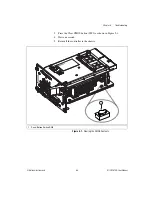
Page 35: ...to store BIOS configuration information Complete the following steps to clear the CMOS contents 1 Power off the chassis 2 Remove the controller from the chassis 3 Press the push button switch as show...

Page 36: ...abVIEW RT Safe Mode when no software is installed LabVIEW RT Safe Mode loads with the basic real time operating system and will automatically attempt to connect to the network using DHCP If DHCP is no...

Page 37: ...Remote Systems category with the assigned name 6 Expand the PXI controller view in the Remote Systems branch and select Software 7 Click the Add Remove Software button in the toolbar to launch the La...

Page 38: ...ine After changing the settings or software reboot the controller with this switch OFF to resume normal operation Switch 3 Disable Startup VI Set this switch to ON to prevent VIs from automatically ru...

Page 39: ...Switches Drivers and Software Files and Directories Installed on Your Hard Drive Your hard drive includes a directory called images in its root that contains software and soft copies of manuals for th...

Page 40: ...ocation process is needed to prevent two resources from connecting to the same trigger line resulting in the trigger being double driven and possibly damaging the hardware At the time of this manual s...

Page 41: ...s 3 In the Devices and Interfaces tree expand PXI System Your PXI Express chassis is already identified and appears in the PXI System tree 4 For each unidentified PXI chassis in the PXI System tree ri...

Page 42: ...slots The use of different size modules in each slot is supported but system performance will be slower than using two matched modules However two mismatched modules could result in better performance...

Page 43: ...CD that allows you to reinstall your operating system onto your hard drive through an external USB CD DVD ROM For more information on these tools refer to KnowledgeBase 2ZKC02OK Hard Drive Recovery an...

Page 44: ...or changing an operating system refer to KnowledgeBase 2ZKC02OK Hard Drive Recovery and OS Installation for PXI and VXI Controllers at ni com support ExpressCard This section provides information on t...

Page 45: ...ease to eject the card Slide the card out of the slot Caution To avoid data loss and other potential issues stop communication with your ExpressCard device before removing it from the NI PXI 8109 In W...

Page 46: ...0 Embedded GPU Serial COM1 9 pin DSUB 16550 RS 232 serial port Ethernet Port 1 LAN RJ45 dual stacked 10 100 1000 Ethernet Intel 82577 Ethernet Port 2 LAN RJ45 dual stacked 10 100 1000 Ethernet Intel 8...

Page 47: ...f the NI PXI 8109 Dimensions are in inches millimeters Figure 3 1 NI PXI 8109 Front Panel Layout and Dimensions 3 727 94 66 3 390 86 11 1 650 41 91 1 256 31 9 1 876 47 65 1 460 37 07 902 22 91 000 0 0...

Page 48: ...Table 3 2 lists and describes the DVI I connector signals Figure 3 2 DVI I Connector Location and Pinout Table 3 2 DVI I Connector Signals Pin Signal Name 1 TMDS Data2 2 TMDS Data2 3 TMDS Data2 4 Shi...

Page 49: ...Ground for 5 V 16 Hot Plug Detect 17 TMDS Data0 18 TMDSData0 19 TMDS Data0 5 Shield 20 Reserved 21 Reserved 22 TMDS Clock Shield 23 TMDS Clock 24 TMDS Clock C1 Analog Red C2 Analog Green C3 Analog Bl...

Page 50: ...d describes the COM1 connector signal Figure 3 3 COM1 Connector Location and Pinout Table 3 3 COM1 Connector Signals Pin Signal Name Signal Description 1 DCD Data Carrier Detect 2 RXD Receive Data 3 T...

Page 51: ...he Ethernet connector signals Figure 3 4 Ethernet Connector Location and Pinout Note The Ethernet controller can perform automatic crossover thus eliminating the need for crossover cables Table 3 4 Et...

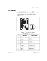
Page 52: ...rt number 777169 01 Figure 3 5 Parallel Port Connector Location and Pinout Table 3 5 10 100 1000 LAN Connector LED States LED Color LED State Condition Top Green Off LAN link is not established On ste...

Page 53: ...SY Device Busy 2 SLCT Select 3 ACK Acknowledge 4 FAULT ERROR Fault 5 PAPEREND Paper End 6 PD0 Data Bit 0 7 PD1 Data Bit 1 8 PD 2 Data Bit 2 9 PD3 Data Bit 3 10 PD4 Data Bit 4 11 PD5 Data Bit 5 12 PD6...

Page 54: ...ts for the Universal Serial Bus USB connectors on the NI PXI 8109 Table 3 7 lists and describes the USB connector signals Figure 3 6 USB Connector Location and Pinout Table 3 7 USB Connector Signals P...

Page 55: ...iggers to or from the backplane trigger bus Figure 3 7 shows the TRIG connector location on the NI PXI 8109 Table 3 8 lists and describes the trigger connector signals Figure 3 7 TRIG Connector Locati...

Page 56: ...al Instruments provides a GPIB mating connector part number 183285 0R2 Figure 3 8 GPIB Connector Location and Pinout Table 3 9 GPIB Connector Signals Pin Signal Name Signal Description 1 DIO1 Data Bit...

Page 57: ...the location and pinouts for the ExpressCard 34 slot on the NI PXI 8109 Table 3 10 lists and describes the ExpressCard connector signals Figure 3 9 ExpressCard 34 Slot Location and Pinout 11 ATN Atten...

Page 58: ...c for future use 6 RESERVED Reserved by spec for future use 7 SMBCLK SMBus Clock 8 SMBDATA SMBus Data 9 1 5V Power 10 1 5V Power 11 WAKE PE Wake 12 3 3VAUX Power 13 PERST PE Reset 14 3 3V Power 15 3 3...

Page 59: ...onboard power supplies is operating outside of the normal limits or the system power supply is out of regulation The LED will also blink green if Windows has been shut down but the chassis power is st...

Page 60: ...tup reboot the NI PXI 8109 and press Delete during the memory tests Refer to the Accessing BIOS Setup section of Chapter 2 Installation and Configuration for more information Can I use the internal ha...

Page 61: ...list of all bootable devices ordered by device type You can set the boot order by altering the Boot Option 1 Boot Option 2 and Boot Option 3 settings To boot from a different device without permanentl...

Page 62: ...nnect a VGA monitor to the NI PXI 8109 A VGA to DVI I adapter National Instruments part number 762559 01 is included with your kit You can use this adapter to connect a VGA monitor to the DVI I port S...

Page 63: ...D ROM drive is available from National Instruments part number 778492 01 Upgrade Information How do I upgrade system memory You can change the amount of installed RAM on the NI PXI 8109 by upgrading t...

Page 64: ...operly When installing memory modules into the memory sockets the lower socket must be populated first followed by the upper socket If a single memory module is used it must be installed in the lower...

Page 65: ...mal operation and the shunt should be left in the default position with the shunt on pins 1 and 2 or with the shunt removed entirely If the shunt is in the wrong position the BIOS will display a warni...

Page 66: ...tion for more information A USB floppy drive is available from National Instruments part number 778492 02 PXI Configuration How do I use the SMB trigger on the front panel For details refer to the PXI...

Page 67: ...t PC If it hangs note the last screen output that you saw for reference when consulting National Instruments technical support What has changed about the system Did you recently move the system Was th...

Page 68: ...Advanced tab of the Display item in the Control Panel Alternately you can try a different monitor preferably a newer and larger one My system boots fine as long as a particular module is not in my cha...

Page 69: ...tional Instruments 5 3 NI PXI 8109 User Manual 3 Press the Clear CMOS button SW2 as shown in Figure 5 1 4 Wait one second 5 Reinstall the controller in the chassis Figure 5 1 Clearing the CMOS Content...

Page 70: ...die L3 cache 4 MB shared between cores Dual Channel DDR3 RAM PC3 8500 2 GB Standard 8 GB Maximum Hard Drive 120 GB or larger Serial ATA Ethernet 10 100 1000 BaseTX 2 ports GPIB IEEE 488 Controller Ye...

Page 71: ...plus three controller expansion slots Compatibility Fully compatible with PXI specification Weight 1 30 kg 2 87 lb typical Environment Maximum altitude 2 000 m 800 mbar at 25 C ambient temperature Po...

Page 72: ...etely dry and free from contaminants before powering on the controller again Storage Environment Ambient temperature Base 40 to 65 C Tested in accordance with IEC 60068 2 1 and IEC 60068 2 2 Extended...

Page 73: ...ut notice Safety This product is designed to meet the requirements of the following standards of safety for electrical equipment for measurement control and laboratory use IEC 61010 1 EN 61010 1 UL 61...

Page 74: ...rtification To obtain product certifications and the Declaration of Conformity DoC for this product visit ni com certification search by model number or product line and click the appropriate link in...

Page 75: ...act an authorized National Instruments service representative For more information about compliance with the EU Battery Directive 2006 66 EC about Batteries and Accumulators and Waste Batteries and Ac...

Page 76: ...ership This program entitles members to direct access to NI Applications Engineers via phone and email for one to one technical support as well as exclusive access to eLearning training modules at ni...

Page 77: ...of conformity This system affords the user protection for electromagnetic compatibility EMC and product safety You can obtain the DoC for your product by visiting ni com certification Calibration Cert...

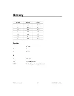
Page 78: ...109 User Manual Glossary Symbol Prefix Value n nano 10 9 micro 10 6 m milli 10 3 k kilo 103 M mega 106 G giga 109 T tera 1012 Symbols Degrees Ohms Percent A A Amperes AC Alternating Current ASIC Appli...

Page 79: ...uctor A type of integrated circuit CompactPCI An adaptation of the PCI specification for industrial and or embedded applications that require a more robust mechanical form factor than desktop PCI Comp...

Page 80: ...ly Erasable Programmable Read Only Memory EMC Electromagnetic Compatibility EMI Electromagnetic interference EPP Enhanced Parallel Port expansion ROM An onboard EEPROM that may contain device specific...

Page 81: ...errupt A means for a device to request service from another device interrupt level The relative priority at which a device can interrupt IRQ Interrupt request signal ISA Industry Standard Architecture...

Page 82: ...essor errors P PCI Peripheral Component Interconnect The PCI bus is a high performance 32 bit or 64 bit bus with multiplexed address and data lines PCI Express Peripheral Component Interconnect Expres...

Page 83: ...squared See also grms RTC Real Time Clock An electronic circuit that maintains the time of day and also can provide timing signals for timesharing operations S s Seconds slave A functional part of a...

Page 84: ...Glossary National Instruments G 7 NI PXI 8109 User Manual V V Volts VGA Video Graphics Array The minimum video display standard for all PCs W W Watts...

Page 85: ...twork Device BBS Priorities Configuration menu 2 15 SATA Configuration menu 2 7 Save Exit menu 2 16 Serial Parallel Port Configuration menu 2 11 Parallel Port menu 2 12 Serial Port menu 2 11 USB confi...

Page 86: ...e 2 26 4 5 Declaration of Conformity NI resources B 2 diagnostic tools NI resources B 1 directories and files installed on hard drive 2 22 documentation conventions used in manual xi how to use this d...

Page 87: ...ical support B 1 I IDE controller using SCSI hard drive in addition 4 1 IEEE 488 2 3 11 images directory 2 23 installation See also configuration injector ejector handle position caution 2 2 NI PXI 81...

Page 88: ...and signals 3 7 trigger connector and signals 3 10 Universal Serial Bus USB connector and signals 3 9 data storage 3 14 description 1 2 flashing the BIOS figure 4 6 front panel dimensions 3 2 features...

Page 89: ...serial port 3 1 Serial Parallel Port Configuration menu 2 11 Parallel Port menu 2 12 Serial Port menu 2 11 shock and vibration specifications A 4 SO DIMM logic block 1 3 software See also drivers inst...

Page 90: ...module 5 2 NI resources B 1 video display 5 2 U Universal Serial Bus USB 3 9 configuration menu 2 10 connector function 1 4 location and pinout figure 3 9 signals table 3 9 overview table 3 1 V VGA o...

Reviews: