Chapter 1
Getting Started
©
National Instruments Corporation
1-7
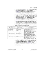
By default, the system controller will control the power supply with the
PS_ON# signals. A logic low on this line will turn the power supply on.
Note
The Inhibit Mode switch on the rear of the chassis must be in the
Default
position
for the system controller to have control of the power supply. Refer to the
section of Chapter 2,
Installation and Configuration
, for details about the Inhibit
Mode switch.
Hybrid Peripheral Slots
The chassis provides four hybrid peripheral slots as defined by the
PXI-5
PXI Express Hardware Specification
: slot 7 and slots 11–13. A hybrid
peripheral slot can accept the following peripheral modules:
•
A PXI Express Peripheral with x4 or x1 PCI Express link to the system
slot or through a switch to the system slot.
•
A CompactPCI Express Type-2 Peripheral with x4 or x1 PCI Express
link to the system slot or through a switch to the system slot.
•
A hybrid-compatible PXI Peripheral module that has been modified by
replacing the J2 connector with an XJ4 connector installed in the upper
eight rows of J2. Refer to the
PXI Express Specification
for details. The
PXI Peripheral communicates through the backplane’s 32-bit PCI bus.
•
A CompactPCI 32-bit peripheral on the backplane’s 32-bit PCI bus.
The hybrid peripheral slots provide full PXI Express functionality and
32-bit PXI functionality except for PXI Local Bus. The hybrid peripheral
slot only connects to PXI Local Bus 6 left and right.
PXI Peripheral Slots
There are nine PXI peripheral slots which will accept PXI or CompactPCI
peripherals: slots 2–6 and slots 15–18. These slots are on the backplane’s
32-bit PCI busses. These slots offer full PXI functionality, but have no
PXI Express features. The 64-bit PCI signals on the P2 connectors are not
connected.


