Chapter 2
Installation and Configuration
2-10
ni.com
Power Inhibit Switch LED Indicator
The chassis power inhibit switch has an integrated LED. This LED
indicates one of four different conditions:
•
If the inhibit switch LED is steady green (not flashing), the chassis is
powered on and operating normally.
•
If the inhibit switch LED is flashing green, the air-intake temperature
has exceeded the chassis operating range.
•
If the inhibit switch LED is flashing red, the power supply outputs are
not within voltage regulation requirements.
•
If the inhibit switch LED is steady red, the system fans or power supply
fan has failed. The remaining fans will automatically be driven high.
Note
If two system fans or both of the power supply fans fail the chassis will shut down
automatically, preventing the chassis and modules from damage due to overheating.
Remote Voltage Monitoring and Control
The NI PXIe-1065 chassis supports remote voltage monitoring and
inhibiting through a female 9-pin D-SUB (DB-9) connector located on
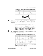
the rear panel. Table 2-1 shows the pinout of the 9-pin D-SUB (DB-9)
connector.
Table 2-1.
Remote Inhibit and Voltage Monitoring Connector Pinout
DB-9 Pin
Signal
1
Logic Ground
2
+5 VDC
3
Reserved
4
+3.3 VDC
5
Inhibit (Active Low)
6
+12 VDC
7
Reserved

