©
National Instruments Corporation
15
18-Slot NI PXIe-1065 Backplane Installation Guide
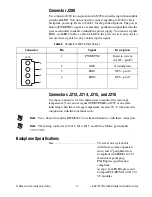
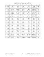
Table 2.
Connector J205 Pin Descriptions
Connector
Pin
Signal
Description
Required
for Basic
Power Up
1
+5V
+5 V power plane
Yes
2
GND
Ground plane
Yes
3
GND
Ground plane
Yes
4
+3.3V
+3.3 V power plane
Yes
5
+12V
+12 V power plane
Yes
6
GND
Ground plane
Yes
7
GND
Ground plane
Yes
8
+12V
+12 V power plane
Yes
9
GND
Ground plane
Yes
10
+12V_SENSE
+12 V sense only, no power
No
11
GND
Ground plane
Yes
12
–12V
–12 V power plane
Yes
13
GND
Ground plane
No
14
OVERTEMP#
Alert of over-temperature
condition in card cage
No
15
GND
Ground plane
No
16
LED1
J200—pin 3
No
17
LED2
J200—pin 4
No
18
+5V_SENSE
+5 V sense only, no power
No
19
GND
Ground plane
No
20
GND
Ground plane
No
21
GND
Ground plane
No
22
SMBCLK
Backplane SMBus clock
No
23
SMBDAT
Backplane SMBus data
No
24
SMBALERT#
Backplane SMBus alert#
No
25
+3.3V_SENSE
+3.3 V sense cnly,
no power
No
26
GND
Ground plane
Yes
27
–12V
–12 V power plane
Yes
28
5VAUX
5VAUX power plane
Yes
1
2
3
4
5
6
7
8
9
10
15
16
21
22
27
28
33
34
35
36
37


