© National Instruments
|
A-7
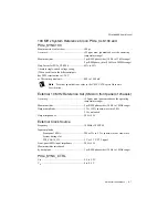
100 MHz System Reference Clock: PXIe_CLK100 and
PXIe_SYNC100
Maximum slot-to-slot skew .............................. 100 ps
Accuracy........................................................... ±25 ppm max. (guaranteed over the operating
temperature range)
Maximum jitter ................................................. 3 ps RMS phase-jitter (10 Hz to 12 kHz range)
2 ps RMS phase-jitter (12 kHz to 20 MHz range)
Duty-factor for PXIe_CLK100......................... 45% to 55%
Absolute single-ended voltage swing
(When each line in the differential pair
has 50 W termination to 1.30 V
or Thévenin equivalent).................................... 400 to 1000 mV
Note
For other specifications, refer to the
PXI-5 PXI Express Hardware
Specification
.
External 10 MHz Reference Out (SMA on front panel of chassis)
Accuracy........................................................... ±25 ppm max (guaranteed over the operating
temperature range)
Maximum jitter ................................................. 5 ps RMS phase-jitter (10 Hz to 1 MHz range)
Output amplitude .............................................. 1 V
PP
±20% square-wave into 50
Ω
2 V
PP
unloaded
Output impedance............................................. 50
Ω
±5
Ω
External Clock Source
Frequency ......................................................... 10 MHz ±100 PPM
Input amplitude
Front-panel SMA...................................... 200 mV
PP
to 5 V
PP
square-wave or sine-wave
System timing slot
PXI_CLK10_IN........................................ 5 V or 3.3 V TTL signal
Front-panel SMA input impedance .................. 50
Ω
±5
Ω
Maximum jitter introduced
by backplane ..................................................... 1 ps RMS phase-jitter (10 Hz to 1 MHz range)
PXIe_SYNC_CTRL
V
IH
.................................................................... 2.0 to 5.5 V
V
IL
..................................................................... 0 to 0.8 V


