© National Instruments
|
I-3
power supply, replacing, 3-2
rack mounting, 2-6
rear view (figure), 1-4
removing power supply (figure), 3-3
unpacking, 1-1
with fan assembly removed (figure), 3-7
PXIe-1066DC backplane
backplane external clock input truth
hybrid peripheral slots, 1-6
interoperability with CompactPCI, 1-5
overview, 1-5
PXI Express peripheral slots, 1-6
PXI local bus, routing, 1-8
PXI peripheral slots, 1-6
PXIe_SYNC_CTRL, 1-11
using as restart (figure), 1-12
specifications, A-6
system controller slot, 1-5
system reference clock, 1-9
default behavior (figure), 1-10
routing (figure), 1-10
system timing slot, 1-6
trigger bus, 1-8
R
rack mount kit dimensions (figure), A-11
rack mounting, 2-6
remote inhibit and fault connector pinout
remote inhibit and fault monitoring, 2-14
remote system monitoring, 2-11
S
safety and caution notices, 2-1
safety ground, connecting to, 2-6
safety specifications, A-4
service interval, 3-1
setting fan speed, 2-5
slot blocker
acoustic emissions
sound power, A-4
sound pressure level (at operator
100 MHz Reference Out BNC, A-7
100 MHz system reference clock
(PXIe_CLK100 and
PXIe_SYNC100), A-7
CE compliance, A-5
chassis cooling, A-3
dimensions (figure), A-9, A-10
electrical, DC output, A-1
electromagnetic compatibility, A-5
environmental
operating environment, A-3
storage environment, A-3
external clock source, A-7
mechanical, A-8
online product certification, A-5
PXI differential star triggers
(PXIe-DSTARA, PXIe-DSTARB,
PXIe-DSTARC), A-8
PXI star trigger, A-8
PXIe_SYNC_CTRL, A-7
rack mount kit dimensions (figure), A-11
safety, A-4
shock and vibration, A-4
system reference clocks, A-6
static discharge damage (caution), 3-1
system configuration file, 2-18
system controller slot
description, 1-5
pinouts
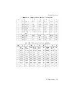
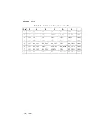
XP1 connector (table), B-2
XP2 connector (table), B-2
XP3 connector (table), B-3
XP4 connector (table), B-3
default behavior (figure), 1-10
routing (figure), 1-10
specifications, A-6


