background image

NI PXIe-1086 Getting Started Guide

|

© National Instruments

|

5

Preparing the Environment

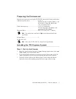
Ensure the environment you are using the NI PXIe-1086 in meets the following specifications.
Ambient temperature range .............................. 0 to 50 °C 

(Tested in accordance with IEC 60068-2-1 and 
IEC 60068-2-2. Meets MIL-PRF-28800F 
Class 3 temperature limits.)

Relative humidity range.................................... 5 to 95%, noncondensing 

(Tested to temperature and humidity levels 
specified in MIL-PRF-28800F)

Maximum altitude............................................. 4600 m (570 mbar) (at 25 °C ambient)

Note

Fan speed selector must be set to 

High

 to meet the maximum altitude 

specification.

Pollution Degree ............................................... 2
For indoor use only.

Note

Refer to the 

NI PXIe-1086 User Manual 

for full specifications.

Installing the PXI Express System

Step 1: Set Up the Chassis

1.

Inspect the chassis interior and exterior for damage. If damage appears to have been caused 
during shipment, file a claim with the carrier.

2.

If you are installing the chassis in an instrument rack, install the rack mount kit for the 
chassis (sold separately). Refer to the instructions supplied with the rack mount kit.

3.

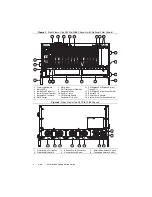
Position the chassis as shown in the following figure, so there is adequate clearance 
between the chassis and surrounding equipment to ensure proper chassis cooling.

Summary of Contents for PXIe-1086

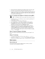
Page 1: ...the Controller 7 Step 3 Install Modules 9 Step 4 Configure the System In Software Using MAX 10 Step 5 Connect Signals to Modules 10 Where To Go Next 10 Maintenance 10 Service Interval 10 Cleaning 11...

Page 2: ...ircuits Operating personnel and service personnel must not remove protective covers when operating or servicing the chassis Adjustments and service to internal components must be undertaken by qualifi...

Page 3: ...rom short circuit and overload with automatic recovery Efficiency 70 typical Power disconnect The AC power cables provide main power disconnect Do not position the equipment so that it is difficult to...

Page 4: ...PXI Filler Panels Optional 9 Removable Feet 10 Fan Door Latch 11 PXI Express Hybrid Peripheral Slots 16x 12 PXI Express PXI Express System Timing Slot 13 PXI Express System Controller Slot 14 Ethernet...

Page 5: ...ust be set to High to meet the maximum altitude specification Pollution Degree 2 For indoor use only Note Refer to the NI PXIe 1086 User Manual for full specifications Installing the PXI Express Syste...

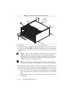
Page 6: ...ted spec the power switch LED blinks green Note If two system fans or both power supply fans fail the chassis shuts down automatically protecting the chassis and modules from damage due to overheating...

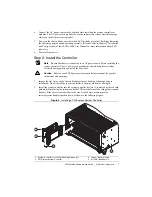
Page 7: ...cord grounds the chassis and protects it from electrical damage while you install the controller Caution Refer to your PXI Express system controller user manual for specific instructions and warnings...

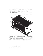
Page 8: ...ler installed in the system controller slot of a chassis Figure 5 PXI Express System Controller Installed in an NI PXIe 1086 Chassis 4 Connect the keyboard mouse and monitor to the appropriate connect...

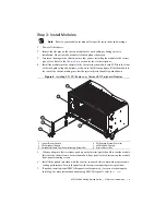
Page 9: ...chassis making sure that the injector ejector handle is pushed down Figure 6 Installing PXI PXI Express or CompactPCI Peripheral Modules 5 When you begin to feel resistance push up on the injector ej...

Page 10: ...abeled PXI System Unidentified Right click this entry to display the pop up menu then select the appropriate system controller model from the Identify As submenu 5 Click the PXI system controller The...

Page 11: ...ts Use just enough moisture to dampen the cloth Caution Do not wash the front or rear panel connectors or switches Cover these components while cleaning the chassis Caution Do not use harsh chemical c...

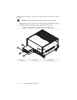
Page 12: ...Before handling the power supply allow the fan to stop spinning 1 Disengage the two captive screws on the rear of the power supply with a flat blade screwdriver 2 Extend the collapsible handle and pu...

Page 13: ...remove the power drawer 1 Loosen the drawer lever captive screws with a flat blade screwdriver until the threads disengage from the chassis frame 2 Rotate the drawer levers to eject the drawer from th...

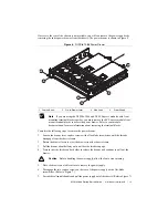
Page 14: ...power drawer from the chassis The power drawer is shown in Figure 8 Note If you are using the NI PXIe 1086 and NI SC Express modules with front mounting terminal blocks together you must remove the SC...

Page 15: ...our National Instruments product Product registration facilitates technical support and ensures that you receive important information updates from NI National Instruments corporate headquarters is lo...

Page 16: ...s You can find information about end user license agreements EULAs and third party legal notices in the readme file for your NI product Refer to the Export Compliance Information at ni com legal expor...

Reviews: