

PXIe-1088 Backplane Overview
Interoperability with CompactPCI
The design of the PXIe-1088 provides you the flexibility to use the following devices in a
single PXI Express chassis:
•
PXI Express compatible products
•
CompactPCI Express compatible 4-Link system controller products
•
CompactPCI Express compatible Type-2 peripheral products
•
PXI peripheral products modified to fit in a hybrid slot
•
Standard CompactPCI peripheral products modified to fit in a hybrid slot
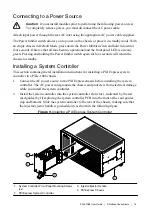
System Controller Slot
The system controller slot is slot 1 of the chassis and is a 4-Link configuration system slot as
defined by the CompactPCI Express and PXI Express specifications. The chassis includes
three system controller expansion slots for system controller modules that are wider than one
slot. These slots allow the system controller to expand to the left to prevent the system
controller from using peripheral slots.
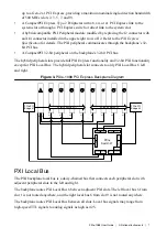
The backplane routes three PCI Express links from the system slot to peripheral slots as x4
links (slots 4, 6, and 8). The other system slot link is routed as a x4 link to the PCI Express
switch providing x1 PCI Express links to the remaining peripheral slots and the two PCI
Express-to-PCI bridges providing a PCI bus to the hybrid peripheral slots.
The system controller slot also has connectivity to some PXI features such as: PXI_CLK10,
PXI Trigger Bus, and PXI Local Bus.
By default, the system controller will control the power supply with the PS_ON# signals. A
logic low on this line will turn the power supply on.
Note
The chassis Inhibit Mode must be set to Default mode for the system
controller to control the power supply.
Hybrid Peripheral Slots
The chassis provides eight (8) hybrid peripheral slots as defined by the
PXI-5 PXI Express
Hardware Specification
: slots 2 through 9. A hybrid peripheral slot can accept the following
peripheral modules:
•
A PXI Express peripheral with x8, x4, or x1 PCI Express link through a switch to the
system slot. Each PXI Express peripheral slot can link up to a Gen-2 x4 PCI Express,
providing a maximum nominal single-direction bandwidth of 2 GB/s (slots 4, 6, and 8) or
6
|
ni.com
|
PXIe-1088 User Guide