background image

© National Instruments

|

1-1

1

Getting Started

The NI PXIe-4302/4303 provides 32 simultaneously sampled filtered analog input channels. 
The NI PXIe-4302 can operate at sample rates up to 5 kS/s/ch and the NI PXIe-4303 can operate 
at sample rates up to 51.2 kS/s/ch. These modules can measure an analog voltage up to 10 V 
when using the TB-4302 and can measure 20 mA current signals when using the TB-4302C. 
Each channel has a 24-bit ADC and selectable digital filters to reject out-of-band noise.

Installation

Refer to the 

NI PXIe-4302/4303 and TB-4302/4302C User Guide and Terminal Block 

Specifications

 document for step-by-step software and hardware installation instructions.

Note

For a complete list of terminal blocks supported by a specific release of 

NI-DAQmx, refer to the Readme, available on the version-specific download page or 
installation media.

Module Specifications

Refer to the 

NI PXIe-4302/4303 Specifications

 document for module specifications.

Module Accessories

Refer to 

ni.com/scexpress

 for information about and a complete listing of supported 

accessories.

Summary of Contents for PXIe-4302

Page 1: ...SC Express NI PXIe 4302 4303 User Manual 32 Ch 24 bit 5 kS s or 51 2 kS s Simultaneous Filtered Data Acquisition Module NI PXIe 4302 4303 User Manual August 2015 377003A 01...

Page 2: ...mail addresses and current events National Instruments Corporate Headquarters 11500 North Mopac Expressway Austin Texas 78759 3504 USA Tel 866 ASK MYNI 275 6964 For further support information refer t...

Page 3: ...ESS FOR A PARTICULAR PURPOSE TITLE OR NON INFRINGEMENT AND ANY WARRANTIES THAT MAY ARISE FROM USAGE OF TRADE OR COURSE OF DEALING NI DOES NOT WARRANT GUARANTEE OR MAKE ANY REPRESENTATIONS REGARDING TH...

Page 4: ...es independent from National Instruments and have no agency partnership or joint venture relationship with National Instruments Patents For patents covering National Instruments products technology re...

Page 5: ...tions 2 8 NI PXIe 4302 4303 Block Diagram 2 8 Signal Acquisition Considerations 2 9 Nyquist Frequency and Nyquist Bandwidth 2 9 ADC 2 9 Operation Modes 2 9 Buffered Mode Acquisitions 2 10 Anti Alias F...

Page 6: ...g Signal Source with Balanced Bias Resistors 2 3 Figure 2 4 Connecting AC Coupled Floating Sources with Low Impedance 2 3 Figure 2 5 Connecting AC Coupled Floating Sources with Balanced Bias Resistors...

Page 7: ...d selectable digital filters to reject out of band noise Installation Refer to the NI PXIe 4302 4303 and TB 4302 4302C User Guide and Terminal Block Specifications document for step by step software a...

Page 8: ...nnecting Voltage Signals Note The TB 4302 terminal block is required when measuring voltage signals Connecting Floating Signal Sources A floating signal source is not connected to the building ground...

Page 9: ...ns yielding better rejection of coupled noise Since the bias resistor is between the negative line of the floating source and AIGND this configuration does not load down the floating source output Fig...

Page 10: ...GND Figure 2 4 Connecting AC Coupled Floating Sources with Low Impedance If the source has high output impedance and is AC coupled balance the signal path as previously described with balanced bias re...

Page 11: ...eferenced Signal Sources With this type of connection the NI PXIe 4302 4303 rejects both the common mode noise in the signal and the ground potential difference between the signal source and the devic...

Page 12: ...a dedicated VSUP terminal to supply voltage to the transducer on each AI channel You can only connect one external voltage supply to the TB 4302C The TB 4302C internally shorts all of the negative AI...

Page 13: ...s of each signal Refer to the NI PXIe 4302 4303 and TB 4302 4302C User Guide and Terminal Block Specifications for signal locations on the terminal blocks AI External Power Supply 2 A Max AISENSE AIGN...

Page 14: ...AI8 AI9 24 AI10 AI11 AI11 23 AIGND AI12 AI13 22 AI14 AI12 AI13 21 AI14 AI15 AI15 20 AIGND AI16 AI17 19 AI18 AI16 AI17 18 AI18 AI19 AI19 17 AIGND AI20 AI21 16 AI22 AI20 AI21 15 AI22 AI23 AI23 14 AIGND...

Page 15: ...teps before being sent to software Refer to the Timing Engines and DSP Streams section for more information about this digital block Table 2 2 I O Connector Signal Descriptions Signal Names Direction...

Page 16: ...lves oversampling the input signal and then decimating and filtering the resulting data to achieve the desired sample rate The NI PXIe 4302 supports rates of 1 S s to 5 kS s The NI PXIe 4303 supports...

Page 17: ...ics some of these components might be represented correctly while others contain aliased artifacts Lowpass filtering to eliminate components above the Nyquist frequency either before or during the dig...

Page 18: ...gital filtering performed by the NI PXIe 4302 4303 produces a delay of many samples worth of time between when an event occurs on the input signal going into the NI PXIe 4302 4303 and when the data as...

Page 19: ...supports Refer to Digital AI Filtering in the NI DAQmx Help for more information about how to configure the filter used Refer to the NI PXIe 4302 4303 Specifications for more information about the cu...

Page 20: ...eness Checking document for more information To access this document go to ni com info and enter the Info Code daqhwtsp Hardware Timed Single Point Acquisition Model The HWTSP data path is optimized f...

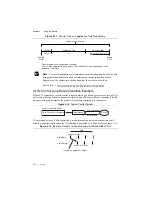
Page 21: ...to the process Figure 2 12 Typical Control System To successfully close a 2 kHz control loop make sure that the time between the time the AI sample is acquired and the time the AO stimulus is generate...

Page 22: ...ore than 480 s will fail to close the 2 kHz control loop When analyzing the bandwidth of the system you must consider the group delay of all the components of the system When using only the NI PXIe 43...

Page 23: ...tions The analog trigger signal can be used as a reference trigger only In a reference triggered acquisition you configure the module to acquire a certain number of pre trigger samples and a certain n...

Page 24: ...nels and to eliminate clock drift between modules in long duration operations You can synchronize the analog input operations on two or more NI PXIe 4302 4303 modules to extend the channel count for y...

Page 25: ...ve module tasks using the DAQmxTaskControl VI Function This sets them up to expect the sync pulse from the master 9 Commit the sync pulse master module task using the DAQmxTaskControl VI Function This...

Page 26: ...of these types and each stream can handle up to 8 channels Therefore it is possible to use all 32 channels in either buffered mode or hardware timed single point mode AI Channels and DSP Streams Whil...

Page 27: ...ingle point mode an error would still be produced by the second task since ai24 in the first task has forced ai24 ai31 to all be buffered mode channels Accessory Auto Detection SC Express modules auto...

Page 28: ...ripheral slot in a PXI Express chassis PXIe_SYNC100 allows modules using PXIe_CLK100 as their reference to recreate the timing of the PXI_CLK10 signal while taking advantage of the lower skew of PXIe_...

Page 29: ...slot of a PXI system but the system will not be able to use the Star Trigger feature PXIe_DSTAR A C PXI Express devices can provide high quality and high frequency point to point connections between...

Page 30: ...libration services to help you maintain accuracy and minimize downtime over the life of your system Visit ni com services for more information Warranty and Repair All NI hardware features a one year s...

Page 31: ...Membership The Standard Service Program SSP is a renewable one year subscription included with almost every NI software product including NI Developer Suite This program entitles members to direct acc...

Reviews: