background image

PXIe-4844 Installation Guide and Specifications

|

© National Instruments

|

5

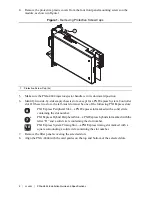
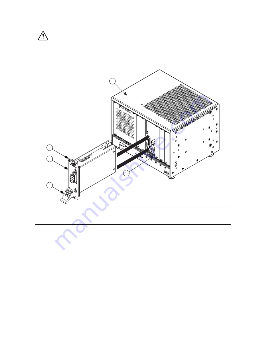
9. Hold the injector/ejector handle down as you slowly slide the module into the chassis until 

the handle catches on the injector/ejector rail, as shown in Figure 2.

Caution

When installing the module, make sure both edges are positioned inside 

the guides and that the module components do not come into contact with adjacent 

modules.

Figure 2.  

Sliding the PXIe-4844 into the Chassis

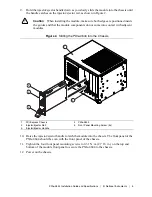
10. Raise the injector/ejector handle to latch the module into the chassis. The front panel of the 

PXIe-4844 should be even with the front panel of the chassis.

11. Tighten the four front panel mounting screws to 0.31 N · m (2.7 lb · in.) on the top and 

bottom of the module front panel to secure the PXIe-4844 to the chassis.

12. Power on the chassis.

1

PXI Express Chassis

2

Injector/Ejector Rail

3

Injector/Ejector Handle

4

PXIe-4844

5

Front Panel Mounting Screw (4x)

1

2

5

4

3

NI

 PXIe-1

073

Summary of Contents for PXIe-4844

Page 1: ...g a single optical fiber The PXIe 4844 requires no calibration as it continuously adjusts its measurements using an on board NIST traceable wavelength reference Caution This icon denotes a caution whi...

Page 2: ...les Caution To ensure the specified EMC performance operate this product only with shielded cables and accessories Caution To ensure the specified EMC performance when using the AUX port install a sna...

Page 3: ...ry for software installation instructions LabVIEW compatibility information and system requirements Installing the PXIe 4844 This section contains installation instructions for the PXIe 4844 Refer to...

Page 4: ...e left most slot must be one of the following PXI Express slots PXI Express Peripheral Slot a PXI Express slot marked with a solid circle containing the slot number PXI Express Hybrid Peripheral Slot...

Page 5: ...me into contact with adjacent modules Figure 2 Sliding the PXIe 4844 into the Chassis 10 Raise the injector ejector handle to latch the module into the chassis The front panel of the PXIe 4844 should...

Page 6: ...e the PXIe 4844 in its original antistatic bag Store the module within its hard shelled plastic case Connecting Sensors The PXIe 4844 has four simplex singlemode LC APC connector ports to connect sens...

Page 7: ...4844 Cleaning Sensors To clean the optical sensors use a ferrule cleaner or follow the standard guidelines 1 Fold a lint free wipe into a compress 2 Moisten the compress with isopropyl alcohol 3 Remov...

Page 8: ...I OSI Explorer to identify and configure the optical sensors connected to the PXIe 4844 Use the Optical Measurement VIs in LabVIEW to perform optical sensing measurements To get started 1 Select Start...

Page 9: ...and connectors visit ni com dimensions and search by module number Dimensions without connectors 13 1 cm 21 4 cm 4 1 cm 5 1 in 8 4 in 1 6 in Weight 213 g 7 5 oz I O connector LC APC Slot requirements...

Page 10: ...for measurement control and laboratory use IEC 60825 1 ED 2 0 2007 03 US CDRH 21 CFR Subchapter J CE Compliance This product meets the essential requirements of applicable European Directives as follo...

Page 11: ...s substances from our products is beneficial to the environment and to NI customers For additional environmental information refer to the Minimize Our Environmental Impact web page at ni com environme...

Page 12: ...ur complete resource for technical support At ni com support you have access to everything from troubleshooting and application development self help resources to email and phone assistance from NI Ap...

Reviews: