


6
|
ni.com
|
PXIe-4844 Installation Guide and Specifications
Removing the PXIe-4844 from the PXIe Chassis
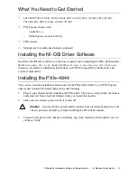
To remove the PXIe-4844 from the PXI Express chassis, complete the following steps:
1. Power off the chassis.
2. Remove any cables or sensors attached to the PXIe-4844.
3. Loosen the four front panel mounting screws on the module.
4. Press the injector/ejector handle down.
5. Slide the module out of the chassis.
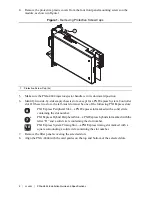
6. Place the PXIe-4844 in its original antistatic bag. Store the module within its hard-shelled
plastic case.
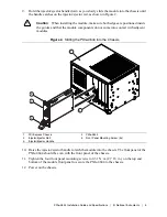
Connecting Sensors
The PXIe-4844 has four simplex singlemode LC/APC connector ports to connect sensors. If
your sensor does not have an LC/APC connector, you need an adapter to connect the sensor to
the LC/APC connector port.
Caution
Connecting damaged or dirty sensors to the module can damage the
LC/APC connector ports on the module. Always clean optical connectors before
connecting to the module.
Caution
Never force an optical connector into an LC/APC connector port.
A ferrule may break and damage the module.


