background image

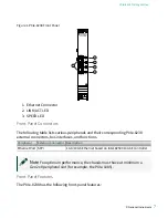
Figure 1. PXIe-8238 Front Panel

NI PXIe-8238

ETH 0

LINK/ACT

LINK/ACT

SPEED

SPEED

ETH 1

2

3

2

3

1

1. Ethernet Connector
2. LINK/ACT LED
3. SPEED LED

Front Panel Connectors

The following table lists various peripherals and their corresponding PXIe-8238

external connectors, bus interfaces, and functions.

Peripheral

External Connector Description

Ethernet Port SFP+

1 Gb/10 Gb Ethernet based on Intel 82599 10 GbE controller

Note

 For optimum performance, the chassis must have at minimum a

Gen2 x8 peripheral slot (for example, the PXIe-1085).

Front Panel Features

The PXIe-8238 has the following front-panel features:

© National Instruments

7

PXIe-8238 Getting Started

Summary of Contents for PXIe-8238

Page 1: ...PXIe 8238 Getting Started 2022 07 06...

Page 2: ...ironment 4 Hardware Installation 4 Powering On the PXIe 8238 6 Powering Off the PXIe 8238 6 Software Installation and Configuration 6 PXIe 8238 Front Panel 6 Removing the PXIe 8238 from a PXI Express...

Page 3: ...stalling your PXIe 8238 module It also describes the module s front panel connectors Unpacking The PXIe 8238 ships in an antistatic package to prevent electrostatic discharge from damaging device comp...

Page 4: ...elative humidity range 10 to 90 noncondensing Tested in accordance with IEC 60068 2 56 Maximum altitude 2 000 m 800 mbar Pollution Degree 2 Indoor use only Note Refer to the PXIe 8238 User Manual for...

Page 5: ...Chassis Controller Peripheral Hybrid H PXIe 8238 Table 1 PXIe 8238 Slot Type Compatibility 6 Align the PXIe 8238 with the card guides on the top and bottom of the slot Hold the handle as you slowly sl...

Page 6: ...ff You also can power off the PXIe 8238 by shutting down the system controller Software Installation and Configuration The PXIe 8238 requires driver software to enable its features For software instal...

Page 7: ...responding PXIe 8238 external connectors bus interfaces and functions Peripheral External Connector Description Ethernet Port SFP 1 Gb 10 Gb Ethernet based on Intel 82599 10 GbE controller Note For op...

Page 8: ...e following steps 1 Power off the chassis 2 Remove any cables that may be attached to the module front panel 3 Unscrew the two bracket retaining screws in the front panel 4 Press the injector ejector...

Page 9: ...uct manuals section at ni com manuals for more information specific to the module with which you are having difficulties NI Services Visit ni com support to find support resources including documentat...

Reviews: