


RMX-10050/10051 User Guide
|
© National Instruments
|
7
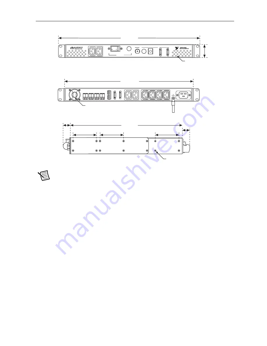
Figure 1.
RMX-10050 Dimensions
Note
DC outputs and DC Inhibit Bus are not available on the
RMX-10050 (785342-01).
438.912 mm
(17.28 in.)
Front View
Rear View
Side View
63.50 mm
(2.50 in.)
63.50 mm
(2.50 in.)
63.50 mm
(2.50 in.)
303.02 mm
(11.93 in.)
19.30 mm
(0.76 in.)
20.066 mm
(0.79 in.)
482.60 mm
(19.00 in.)
44.196 mm
(1.74 in.)
Black #27038
All Outside Surfaces
Exhaust Air
#4–4 X 0.20 DP Holes
2X Both Sides
Off
Off
On
On
Breaker
Breaker
Main Breaker
Main Breaker
GROUP AG
R
O
U
P
A
On
On
Main Power
Main Power
Powered
Powered
Control
Control
Control
Control
Switched Outlets
Switched Outlets
Switched Outlets
Switched Outlets
Outlet Control Bus
Outlet Control Bus
Local/On
Local/On
Off
Off
A
Remote
Remote
DC 1
DC 1
+
–
+
–
+
–
+
–
DC 1
DC 1
DC 1
DC 1
DC 1
DC 1
GROUP AG
R
O
U
P
A
GROUP BG
R
O
U
P
B
DC INHIBITD
C
I
N
H
IB
IT
Enable
Enable
Disable
Disable
Return
Return


