Connecting CAN Networks
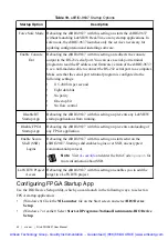
The sbRIO-9637 is populated with one IDC header to provide connections to a CAN bus. This
connector has pins for CAN_H and CAN_L, which can connect to the CAN bus signals. The
CAN port uses an NXP PCA82C251T high-speed CAN transceiver that is fully compatible
with the ISO 11898 standard and supports baud rates up to 1 Mbps.
The port has two common pins (GND) that serve as the reference ground for CAN_H and
CAN_L. You can connect the CAN bus reference ground (sometimes referred to as CAN_V-)
to one or both COM pins. The port also has an optional shield pin (SHLD) that can connect to
a shielded CAN cable. Connecting SHLD may improve signal integrity and EMC
performance.
CAN Bus Topology and Termination
A CAN bus consists of two or more CAN nodes cabled together. The CAN_H and CAN_L
pins of each node are connected to the main CAN bus cable through a short connection called
a stub. The pair of signal wires, CAN_H and CAN_L, constitutes a transmission line. If the
transmission line is not terminated, signal changes on the bus cause reflections that can cause
communication errors. The CAN bus is bidirectional, and both ends of the cable must be
terminated. However, only the two nodes at the far end of the cable, not every node on the bus,
require termination resistors.
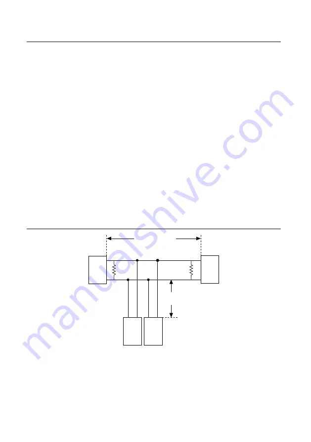
The following figure shows a simplified diagram of a CAN bus with multiple CAN nodes and
proper termination resistor (Rt) locations.
Figure 32. CAN Bus Topology and Termination Resistor Locations
CAN
Node
CAN
Node
CAN
Node
Rt
Rt
CAN
Node
CAN_H
CAN_L
CAN_H
Bus Cable Length
CAN_L
Stub
Length
CAN_H
CAN_L
CAN_H
CAN_L
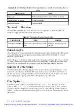
Cable Specifications
Cables must meet the physical medium requirements specified in ISO 11898, shown in the
following table. Belden cable (3084A) meets all these requirements and is suitable for most
applications.
NI sbRIO-9637 User Manual
|
© National Instruments
|
43
Artisan Technology Group - Quality Instrumentation ... Guaranteed | (888) 88-SOURCE | www.artisantg.com


