SC-2062 Board
Chapter 4
SC-206X Series User Manual
4-2
© National Instruments Corporation
The 26-pin connector (J1) attaches to the appropriate SC-205X Series board via a 26-pin
conductor cable. You can connect an ex5 V power supply to the external power screw
terminal block (J2) if required. To determine if an ex5 V supply is necessary, refer to
Internal or External Power Selection in Chapter 5. Switch S1 selects between internal and
external power. The driver amplifies the logic-level signals from the host data acquisition board
to levels sufficient to drive the relays. The relays open and close connections made at the screw
terminals (J3 through J10).
There are three connections per channel–NC, NO, and COM. There is a small gap between
screw terminal blocks of adjacent channels. Figure 4-1 shows the locations of the screw
terminals and other major board components.
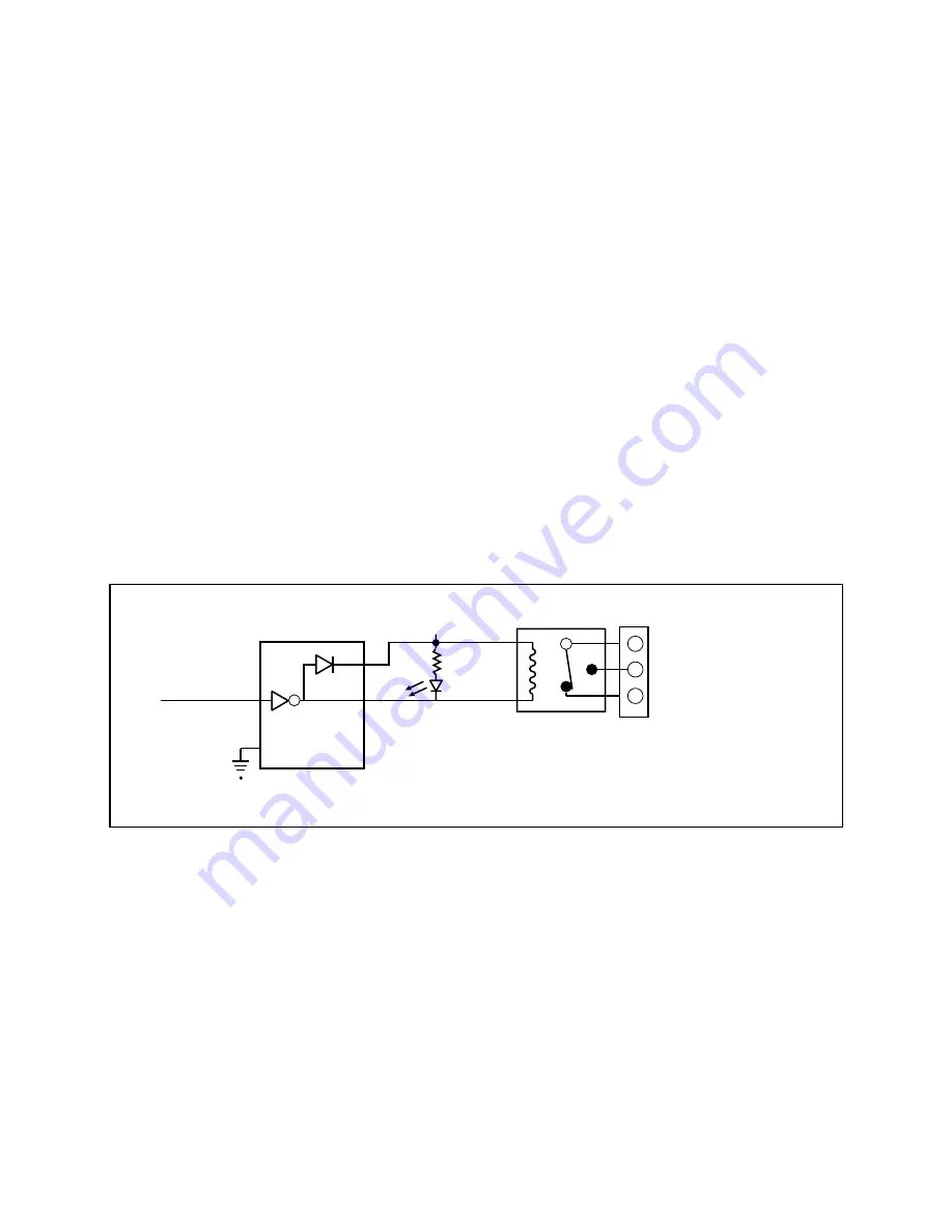
The SC-2062 has eight sets of relay contacts. While a channel receives a low output signal, the
relay for that channel remains unenergized and the NC contact shorts to COM while the NO
contact remains open. When a high output signal is present on a channel, the relay for that
channel is energized, and the NO contact shorts to COM while the NC contact is open. A green
indicator LED just above each relay illuminates when the relay is energized. Each energized
relay requires about 60 mA, so power consumption goes up dramatically as the number of
energized relays increases. To reduce power consumption and to help extend relay life, control
the signals so that relays are energized for only the shortest periods of time and simultaneously a
minimal number of relays are energized. Figure 4-2 shows the 5 V onboard equivalent circuit
for the SC-2062 board.
NC (normally closed)
NO (normally open)
COM (common)
+5 V
1 k
Ω
LED
10
ULN2803
High-Current Buffer
9
(From
plug-in
board)
DIO
X
J1
J
Figure 4-2. SC-2062 5 V Onboard Equivalent Circuit
Warnings: When connecting or disconnecting signal lines to the screw terminals, you must
power off the lines. Potential differences between the lines and the SC-2062
ground create a shock hazard while connecting the lines.
Connections, including power signals to ground and vice versa, that exceed any of
the maximum input or output signal ratings on the SC-2062 can result in damage to
any or all of the boards connected to the SC-206X Series, to the host computer, and
to the SC-2062 board. National Instruments is not liable for any damages resulting
from incorrect signal connections.


