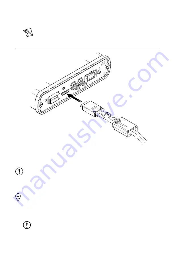
2.
To ensure the Molex
™
Nano-Pitch I/O
™
cable stays inserted, slide the strain relief
assembly over the Molex
™
Nano-Pitch I/O
™
cable body and screw it into position in the
front panel.
Note
The strain relief assembly ships with Molex Nano-Pitch cables
purchased from NI. To ensure an uninterrupted connection, NI recommends,
but does not require, the use of the strain relief assembly.
Figure 3. Connecting the Strain Relief Assembly
SCB-12
Aux I/O Breakout Accessory
DIO
POWER
#6-32
DIO 5
DIO 6
DIO 7
GND
DIO 2
DIO 3
DIO 4
5V A
UX
MGT REF CLK+
DIO 0/
MGT REF CLK+
DIO 1/
Connecting to the DIO/MGT REF CLK Ports
Screw a standard SMA cable into one or both of the DIO/MGT REF CLK ports.
Notice
Using signal voltages outside of the range specified for the FlexRIO
module you connect to the SCB-12 could damage the SCB-12 and any instruments
connected to it. For maximum voltage specifications, refer to the documentation for
the connected hardware. NI is not liable for any damage resulting from using
voltages outside of the recommended range.
Tip
To ease cable installation difficulties when connecting to multiple ports, NI
recommends connecting to the DIO/MGT REF CLK ports first.
Connecting to the DIO Spring Terminals
1.
Strip and prepare the wires to connect to the DIO signals you want to access.
Notice
To ensure the EMC performance specified for the connected hardware,
NI recommends using a multiconductor cable with an overall shield to connect
SCB-12 User Guide
|
© National Instruments Corporation
|
7


