Note
You must use the external power supply included in the SCB-12 kit, NI
part number 723537-01, to power an optical QSFP or QSFP+ cable.
3.
The power LED on the SCB-12 front panel indicates a connection to external power.
After connecting the external power supply included in your kit, ensure the power LED is
lit.
4.
Connect your optical or electrical QSFP or QSFP+ cable to PORT 0.
Note
on page 5 for recommended
QSFP and QSFP+ cable specifications.
Using the Optional Ground Lug
The SCB-12 provides an optional ground lug on the front panel.
Notice
To mitigate ground loops or conducted noise that may impair the
functionality of the SCB-12, attach a thick wire or braided cable from the system
ground to the ground lug on the SCB-12 front panel.
Mounting the SCB-12 on a DIN Rail with the
NI 9913 Mounting Kit
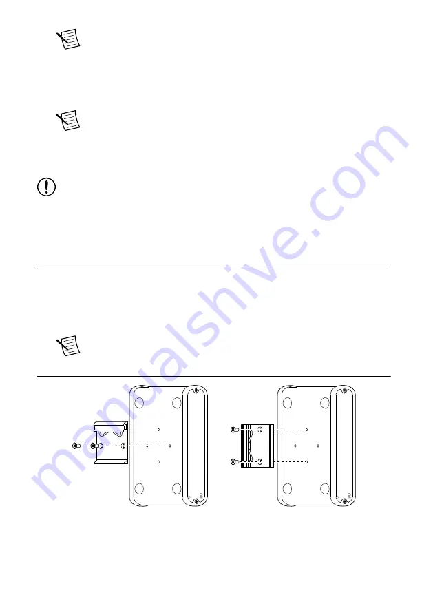
The NI 9913 DIN rail mounting kit contains a clip for mounting the SCB-12 on a standard
35 mm DIN rail. The four holes on the bottom of the SCB-12 allow it to be mounted in
multiple orientations.
1.
Using a #2 Phillips screwdriver and the two FLH #6-32 × 5/16" screws included in the
NI 9913 DIN rail mounting kit, fasten the DIN rail clip to the SCB-12.
Note
Use only the screws provided in the DIN rail kit. Using longer screws
may damage the SCB-12.
Figure 6. DIN Rail Clip Installation
2.
Clip the SCB-12 onto the DIN rail with the larger lip of the DIN rail clip positioned up.
SCB-12 User Guide
|
© National Instruments Corporation
|
9


