to spring terminals. Terminate the cable shield to one of the PCB mounting
screws.
2.
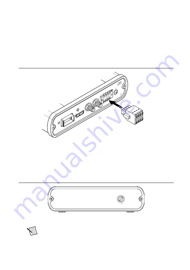
Align the 8-pin female connector included in your kit to the DIO spring terminals and the
retention screw holes on the SCB-12 front panel. Use a 2.5 mm flathead screwdriver to
loosely screw the attached retention screws into the front panel.
3.
Use the flathead screwdriver to open the spring terminals and insert the prepared wires.
4.
After inserting the wires, use your thumb to press firmly on the 8-pin female connector
until it fully seats into the front panel. Use the flathead screwdriver to tighten the
retention screws.
Figure 4. Connecting the 8-Pin Female Connector to the DIO Spring Terminals
SCB-12
Aux I/O Breakout Accessory
DIO
POWER
#6-32
DIO 5
DIO 6
DIO 7
GND
DIO 2
DIO 3
DIO 4
5V A
UX
MGT REF CLK+
DIO 0/
MGT REF CLK+
DIO 1/
Connecting to PORT 0
Before you begin, refer to
on page 10 for maximum voltage
and power specifications.
1.
To connect an optical QSFP or QSFP+ cable at PORT 0, first connect the external power
supply included in your kit to the power connector on the back panel of the SCB-12.
Figure 5. SCB-12 Back Panel
5.9 V
9 W MAX
2.
Plug the external power supply into AC power.
Note
Electrical QSFP or QSFP+ cables do not require the external power
supply included in your kit.
8
|
ni.com
|
SCB-12 User Guide


