Appendix D
SCXI-1121 Front Connector
D-4
www.natinst.com
Further information is given in Chapter 2,
Configuration and Installation
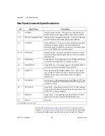
C18
EX2–
Negative Excitation Output 2—This pin is connected to the
excitation channel 2 negative output.
A20
CH2+
Positive Input Channel 2—This pin is connected to the input
channel 2 positive input.
C20
CH2–
Negative Input Channel 2—This pin is connected to the input
channel 2 negative input.
A22
EGND1
Excitation Ground 1—This pin connects to the excitation ground 1
via a 51 k
Ω
resistor.
A24
EX1+
Positive Excitation Output 1—This pin is connected to the
excitation channel 1 positive output.
C24
EX1–
Negative Excitation Output 1—This pin is connected to the
excitation channel 1 negative output.
A26
CH1+
Positive Input Channel 1—This pin is connected to the input
channel 1 positive input.
C26
CH1–
Negative Input Channel 1—This pin is connected to the input
channel 1 negative input.
A28
EGND0
Excitation Ground 0—This pin connects to the excitation ground 0
via a 51 k
Ω
resistor.
A30
EX0+
Positive Excitation Output 0—This pin is connected to the
excitation channel 0 positive output.
C30
EX0–
Negative Excitation Output 0—This pin is connected to the
excitation channel 0 negative output.
A32
CH0+
Positive Input Channel 0—This pin is connected to the input
channel 0 positive input.
C32
CH0–
Negative Input Channel 0—This pin is connected to the input
channel 0 negative input.
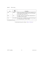
Pin
Signal
Name
Description

