©
National Instruments Corporation
5
SCXI-1122 Calibration Procedure
Setting Up the Module
Complete the following steps to set up the SCXI-1122 module for
verification:
1.
Install the SCXI-1122 module in slot 4 of the SCXI chassis.
2.
Connect a 68-to-68-pin cable between the SCXI-1122 module and the
E Series DAQ device.
3.
Configure the hardware with Measurement & Automation Explorer
(MAX). For more information about configuring the calibration
system, refer to the E Series DAQ device and SCXI-1122 module
documentation.
Verifying the Operation of the Module
These verification procedures determine how well the SCXI-1122 module
is meeting its test limits. You can use this information to select the
appropriate calibration interval for your application.
Verifying Analog Input Offsets
Complete the following steps to verify the analog input offsets:
1.
Read the
section in this document.
2.
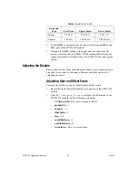
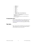
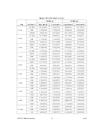
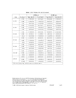
Refer to Table 3 for the limits to verify. Although NI recommends
verifying all ranges and gains, you can save time by checking only
those ranges used in your application.
3.
Ensure that the E Series DAQ device is connected to the SCXI-1122
module.
4.
Call
Calibrate_E_Series
to minimize the uncertainty associated
with the E Series DAQ device. Set the following parameters:
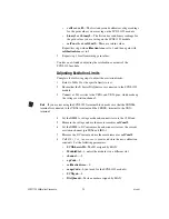
•
deviceNumber
—The value assigned by MAX
•
calOp
—
ND_SELF_CALIBRATE
•
setOfCalConstants
—
ND_USER_EEPROM_AREA
•
calRefVolts
—0.0
5.
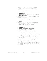
Call
AI_Configure
to set the E Series DAQ device in bipolar mode.
Set the following parameters:
•
deviceNumber
—The value assigned by MAX
•
chan
—0
•
inputMode
—0
•
inputRange
—0
•
polarity
—0
•
driveAIS
—0


