Signal Connections
Chapter 3
SCXI-1122 User Manual
3-4
© National Instruments Corporation
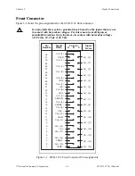
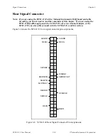
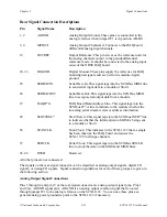
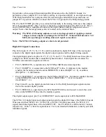
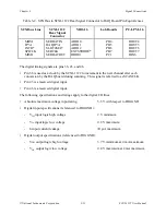
Front Signal Connection Descriptions
Pin
Signal Name
Description
A1
TEMP-
Temperature Sensor Reference–This pin is tied to the
temperature sensor reference in the terminal block and to
the isolation amplifier negative input in the module.
A3
TEMP+
Temperature Sensor Output–This pin connects the
temperature sensor output to the amplifier input selector.
A7
+5 V
+5 VDC Isolated Source–This pin, which powers the
temperature sensor on the terminal block, has 0.5 mA of
source not protected.
A11
VEX/2
Half Voltage Excitation Output–This pin connects to the
internal bridge completion network for quarter-bridge and
half-bridge measurements. Protected to
±
20 V maximum.
A13
VEX-
Negative Voltage Excitation Output–This pin is connected
to the voltage excitation negative output.
A15
SENSE-
Negative Voltage Sense–This pin must be tied to VEX- at
the load for remote sensing. When using the SCXI-1322
terminal block, this pin is connected to VEX/SENSE-
screw terminals.
A17
SENSE+
Positive Voltage Sense–This pin must be tied to VEX+ at
the load for remote sensing. When using the SCXI-1322
terminal block, this pin is connected to VEX/SENSE+
screw terminals. This pin is not protected.
A19
VEX+
Positive Voltage Excitation Output–This pin is connected
to the voltage excitation positive output.
A21
IEX-
Negative Current Excitation Output–This pin is connected
to the current excitation negative output.
A23
IEX+
Positive Current Excitation Output–This pin is connected to
the current excitation positive output.
A5, A9,
No Connect–Do not connect any signal to these pins.
A25-A29
A31
RSVD
Reserved–This pin is reserved. Do not connect any signal
to this pin.
B32-B2
CH+(0:15)
Positive Input Channel–These pins are connected to the
positive input channels 0 through 15 respectively.
C31-C1
CH-(0:15)
Negative Input Channel–These pins are connected to the
negative input channels 0 through 15 respectively.

