Chapter 3
Signal Connections
© National Instruments Corporation
3-5
SCXI-1122 User Manual
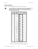
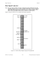
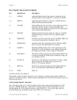
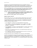
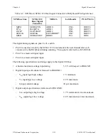
The signals on the front connector are all analog except pins A7, and A31, which are digital. The
analog signals are grouped into analog input channels, excitation channels, and temperature
sensor signals. Signal connection guidelines for each of these groups are described in the
following sections.
Notes:
All pins are overvoltage protected to 250 Vrms except for pin A7 (+5 V signal), pin 31
(RSVD), pin A17 (SENSE+), and pin A11 (VEX/2).
All inputs and outputs on the front connector are isolated. The maximum working
common-mode voltage to earth is 480 Vrms and between channels is 250 Vrms.
Analog Input Channel Signal Connections
The positive input channel signal terminals are located in column B of the connector. Their
corresponding negative input channel signal terminals are located in column C of the connector.
Each input corresponds to a separate relay that are all multiplexed into the amplifier input
selector. In addition to the relay inputs, the temperature sensor output from the terminal block–
located on pins A3 (TEMP+) and A1 (TEMP-)–is also connected to the amplifier input selector.
All inputs are fully isolated from earth ground and are in a floating single-ended configuration;
hence, you can measure signals that have a common-mode voltage up to 480 Vrms. Notice that
the maximum allowable channel-to-channel common-mode voltage is 250 Vrms.
Warning:
E
XCEEDING THE INPUT SIGNAL RANGE RESULTS IN DISTORTED SIGNALS
.
Exceeding the maximum input voltage rating (250 Vrms between positive and
negative inputs or outputs, 250 Vrms between input or output channels, and
480 Vrms between input or output channels and earth ground) can damage the
SCXI-1122, the SCXIbus, and the DAQ board. National Instruments is
NOT
liable for any damages or injuries resulting from such signal connections.
For better noise immunity, and if all the measured signals are floating, connect the negative input
channels to chassis ground on the terminal block using the solder lug attached to the strain-relief
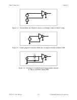
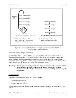
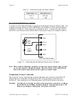
bar. Figure 3-2 shows how to connect a ground-referenced signal. Figure 3-3 shows how to
connect a floating signal. Figures 3-4 and 3-5 show how to connect AC-coupled signals.

