Chapter 3
Signal Connections
© National Instruments Corporation
3-7
SCXI-1122 User Manual
Vs
R
b
C
c
Vcm
+
-
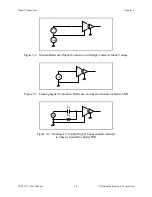
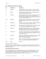
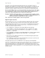
Figure 3-5. AC-Coupled Signal Connection with High Common-Mode Voltage
For AC-coupled signals, connect an external resistor from the positive input channel to the signal
reference to provide the DC path for the positive input bias current. Typical resistor values range
from 100 k
Ω
to 1 M
Ω
. This solution, although necessary in this case, lowers the input
impedance of the input channel amplifier and introduces an additional offset voltage proportional
to the input bias current and to the resistor value used. The typical input bias current of the
amplifier consists of
±
80 pA and a negligible offset drift current. A 100 k
Ω
bias resistor results
in
±
8
µ
V of offset, which is insignificant in most applications. However, if you use larger
resistors, significant input offset may result. To determine the maximum offset the biasing
resistor will introduce, use the following equation:
V
ofsbias
= I
bias
x R
bias
The input signal range of an SCXI-1122 input channel is
±
10 V/ G
total
referenced to its negative
input, where G
total
is equal to the gain selected on the SCXI-1122. In addition, the input channels
are overvoltage protected to 250 Vrms with power on or off at a maximum of 2.5 mArms sink or
source.
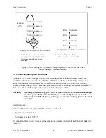
Note: The SCXI-1122 input multiplexer is composed of relays. Relays have a certain life
expectancy, as listed in Appendix A, Specifications. To avoid mechanical wear on the
relays, and when you are acquiring a large number of points per channel and
averaging, you should acquire the n samples on a given channel before proceeding to
the next channel. For example, rather than performing 100 scans and taking a single
sample from each channel during each scan, as shown in Figure 3-6a, acquire
100 points on each channel then switch to the next channel and acquire a new set of
samples, as shown in Figure 3-6b.

