©
National Instruments Corporation
11
SCXI-1122 Calibration Procedure
3.
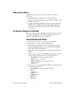
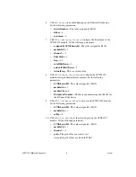
Call
SCXI_Single_Chan_Setup
to configure the SCXI-1122
module for single channel measurements. Set the following
parameters:
•
SCXIchassisID
—The value assigned by MAX
•
moduleSlot
—1
•
moduleChan
—0
•
DAQdeviceNumber
—The device number assigned by MAX for
the E Series DAQ device
4.
Call
SCXI_Calibrate_Setup
to auto-zero the SCXI-1122 module.
Set the following parameters:
•
SCXIchassisID
—The value assigned by MAX
•
moduleSlot
—1
•
calOp
—2
5.
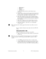
Call
SCXI_Set_Gain
to set the selected gain on the SCXI-1122
module. Set the following parameters:
•
SCXIchassisID
—The value assigned by MAX
•
moduleSlot
—0
•
channelSet
— –1
•
gainSet
—The first gain value you want to adjust
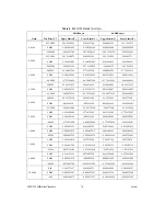
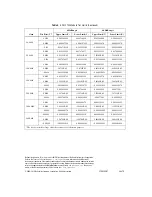
Acceptable gain values are listed in Table 3.
6.
Connect the calibrator to analog input channel 0. If you are using
an SCXI-1322 terminal block connected to the SCXI-1122 module,
connect the calibrator to the CH0+ and CH0– inputs.
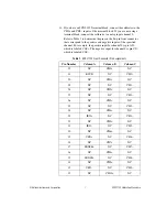
Refer to Table 1 to determine the pins on the 96-pin front connector
that correspond to the positive and negative inputs of the specified
channel. For example, the positive input for channel 0 is pin A32,
which is labeled
CH0+
. The negative input for channel 0 is pin C31,
which is labeled
CH0–
.
7.
Connect the DMM to the output of channel 0 by using the 50-pin
breakout connector on the SCXI-1349 adapter.
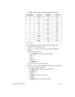
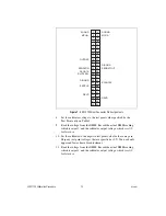
Refer to Figure 1 to determine the pins on the 50-pin rear connector
that correspond to the positive and negative outputs for the specified
channel. For example, the positive output for channel 0 is pin 3, which
is labeled
MCH0+
. The negative output for channel 0 is pin 4, which
is labeled
MCH0–
.


