background image

SCXI-1122 Calibration Procedure

14

ni.com

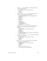
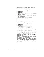
volt1

 and

 volt2

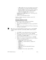
—The first and second calibrator voltage readings 

for the gain values you are saving on the SCXI-1122 module

binary1

 and 

binary2

—The first and second binary readings for 

the gain values you are saving on the SCXI-1122 module

calConst1

 and 

calConst2

—These are return values

Repeat this step with 

calibrationArea

 set to 1, and then again with 

calibrationArea

 set to 3.

2.

Repeat step 1 for all remaining gain values.

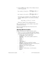
You have now finished adjusting the calibration constants of the 
SCXI-1122 module.

Adjusting Excitation Limits

Complete the following steps to adjust the excitation limits:

1.

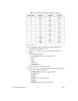
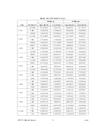
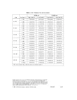
Refer to Table 2 for the specific limits to test.

2.

Ensure that the E Series DAQ device is connected to the SCXI-1122 
module.

3.

Connect a 15 

Ω

 resistor to the VEX+ and VEX– pins, which make up 

the voltage excitation channel.

Note

If you are not using the SCXI-1322 terminal block, make sure that the SENSE+ 

terminal is connected to the VEX+ terminal and the SENSE– terminal to the VEX– 
terminal.

4.

Set the DMM to voltage mode and connect it across the 15 

Ω

 load.

5.

Measure the voltage and use the measurement as 

calConst2

.

6.

Set the DMM to DC current mode and connect it across the current 
excitation channel (pin IEX+ and IEX–).

7.

Measure the DC current and use the measurement as 

calConst1

.

8.

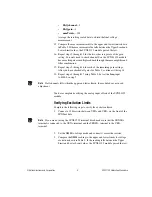
Call 

SCXI_Cal_Constants

 to create and store the new calibration 

constants. Set the following parameters:

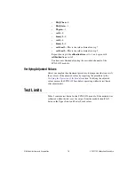
SCXIchassisID

—The ID assigned by MAX

ModuleSlot

—1, unless the module is in a different slot

channel

— –2

opCode

—3

calibrationArea

—0

rangeCode

—0 (not used for the SCXI-1122 module)

SCXIgain

—0

DAQboard

—Device number assigned by MAX

Summary of Contents for SCXI -1122

Page 1: ...pment and Other Test Requirements 2 Test Equipment 2 Instruments 3 Connectors 3 Software and Documentation 3 Software 3 Documentation 3 Test Conditions 4 Calibration 4 Setting Up the Module 5 Verifyin...

Page 2: ...can affect measurement accuracy as a module ages Calibration restores these components to their specified accuracy and ensures that the module still meets NI standards How Often Should You Calibrate...

Page 3: ...n This section describes the software and documentation you need to calibrate the SCXI 1122 module Software This calibration procedure requires the latest version of the Traditional NI DAQ Legacy driv...

Page 4: ...ent during calibration Keep connections to the SCXI 1122 module and the terminal block short Long cables and wires act as antennae picking up extra noise and thermal offsets that can affect measuremen...

Page 5: ...ct the appropriate calibration interval for your application Verifying Analog Input Offsets Complete the following steps to verify the analog input offsets 1 Read the Test Conditions section in this d...

Page 6: ...e 8 Call SCXI_Single_Chan_Setup to configure the SCXI 1122 module for single channel measurements Set the following parameters SCXIchassisID The value assigned by MAX moduleSlot 1 moduleChan 0 DAQdevi...

Page 7: ...tive and negative inputs of the specified channel For example the positive input for channel 0 is pin A32 which is labeled CH0 The negative input for channel 0 is pin C31 which is labeled CH0 Table 1...

Page 8: ...urned to the buffer variable 14 Call SCXI_Scale to convert the acquired readings into scaled voltage values Set the following parameters SCXIChassisID The value assigned by MAX moduleSlot 0 channel 0...

Page 9: ...gains for Table 3 continue with step 18 18 Repeat steps 4 through 17 using Table 3 but set the freq input to 4000 0 in step 7 Note If all channels fall within the upper and lower limits the module do...

Page 10: ...one for adjusting calibration constants and one for adjusting excitation Adjusting Gain and Offset Errors Complete the following steps to adjust gain and offset errors 1 Ensure that the E Series DAQ d...

Page 11: ...ptable gain values are listed in Table 3 6 Connect the calibrator to analog input channel 0 If you are using an SCXI 1322 terminal block connected to the SCXI 1122 module connect the calibrator to the...

Page 12: ...ator to the negative test point value for the same gain Skip any test point voltages that are specified as 0 V You need only upper and lower limits for adjustment 11 Read the voltage from the DMM Reco...

Page 13: ...llowing steps to adjust the calibration constants 1 Call SCXI_Cal_Constants to create and store the new calibration constants in the memory of the SCXI 1122 module Call this function for each gain set...

Page 14: ...Q device is connected to the SCXI 1122 module 3 Connect a 15 resistor to the VEX and VEX pins which make up the voltage excitation channel Note If you are not using the SCXI 1322 terminal block make s...

Page 15: ...annels of the SCXI 1122 module Verifying Adjusted Values After you complete the adjustment procedure it is important that you verify the accuracy of the adjusted values by repeating the procedure in t...

Page 16: ...1672 48 89579119 49 10420881 0 2000 24 5000 24 55178536 24 44821464 24 5522814 24 4477186 0 0000 0 01434936 0 01434936 0 014845403 0 014845403 24 5000 24 44821464 24 55178536 24 4477186 24 5522814 0 5...

Page 17: ...98121183 0 097868098 0 098131902 100 0000 0 0490 0 049065034 0 048934966 0 049069951 0 048930049 0 0000 3 6712E 05 3 6712E 05 4 16291E 05 4 16291E 05 0 0490 0 048934966 0 049065034 0 048930049 0 04906...

Reviews: