©
National Instruments Corporation
9
SCXI-1122 Calibration Procedure
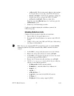
•
DAQchannel
—0
•
DAQgain
—1
•
numPoints
—100
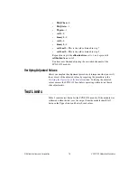
Average the resulting scaled data to obtain the final voltage
measurement.
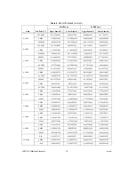
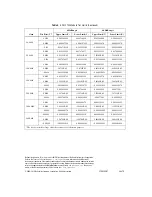
15. Compare the measurement result to the upper and lower limits shown
in Table 3. If the measurement value falls between the Upper Limit and
Lower Limit values, the SCXI-1122 module passed the test.
16. Repeat steps 5 through 15 for the two other test points of the gain
setting. You only need to check channel 0 on the SCXI-1122 module
because all inputs are multiplexed back through the same amplifier and
filter combination.
17. Repeat steps 5 through 16 for each of the remaining gain settings.
After you have checked all gains for Table 3, continue with step 18.
18. Repeat steps 4 through 17 using Table 3, but set the
freq
input
to 4000.0 in step 7.
Note
If all channels fall within the upper and lower limits, the module does
not
need
adjustment.
You have completed verifying the analog input offsets of the SCXI-1122
module.
Verifying Excitation Limits
Complete the following steps to verify the excitation limits:
1.
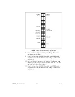
Connect a 15
Ω
resistor between VEX+ and VEX– on the front of the
SCXI module.
Note
If you are not using the SCXI-1322 terminal block, make sure that the SENSE+
terminal is connected to the VEX+ terminal and the SENSE– terminal to the VEX–
terminal.
2.
Set the DMM to voltage mode and connect it across the resistor.
3.
Compare the DMM reading to the upper and lower limits for voltage
excitation shown in Table 2. If the reading falls between the Upper
Limit and Lower Limit values, the SCXI-1122 module passed the test.


