5
MIO Board
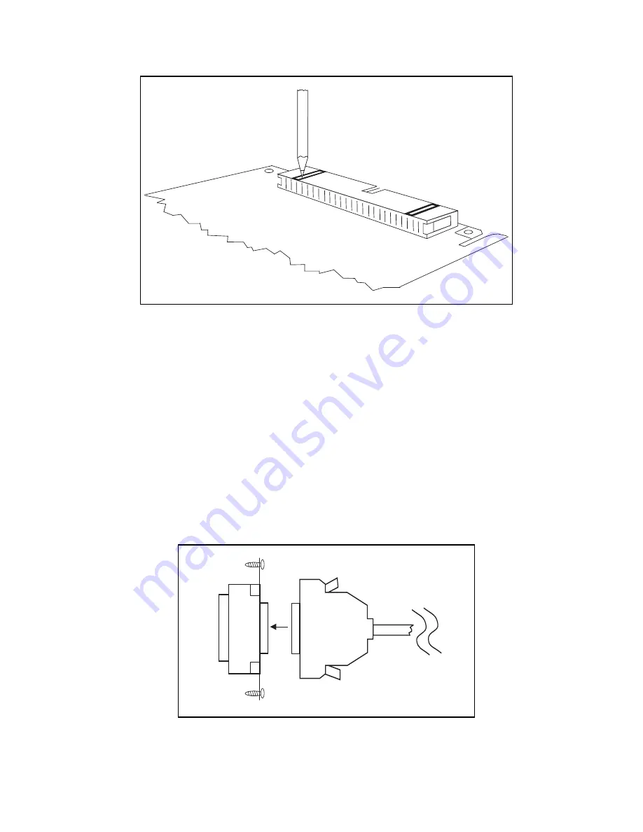
Figure 4. Removing the Key Inserts
e. Identify the proper replacement bracket from your kit. If you have an NB Series board,
use the bracket marked 745402-01; if you have an AT Series board, use the bracket
marked 745403-01. The bracket that you use should look like the one you remove,
except that the new one has an extra tab that attaches to the grounding strap.
f. Install the new bracket by aligning the bracket with the holes in your MIO board and
screw in the two mounting screws.
6. Install your MIO board in a slot in your computer, following the instructions in your MIO
board user manual.
7. Connect the 68-pin connector (the end without the grounding strap) of the SCXI-1345
cable to the 68-pin connector of the SCXI-1345 adapter board as shown in Figure 5.
Adapter
Board
Shielded Cable
Figure 5. Cable to Adapter Board Connection


