©
National Instruments Corporation
5
SCXI-1381K Installation Guide
6.
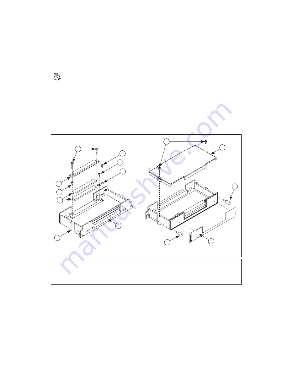
Use a Number 1 Phillips-head screwdriver to attach the circuit board
to the base with the two 4–40 by 0.29 in. shoulder screws.
7.
Attach the terminal block cover to the terminal block base with two
4–40 captive cover screws. These screws also ground the cover.
Note
The 4-40 captive cover screws become captive screws once they are installed for the
first time.
8.
Attach the thumbscrews.
The assembly is complete.
Use the thumbscrews to attach the assembled terminal block to an
SCXI module. As needed, connect signal wires to your custom circuit
board.
Figure 3.
Parts Locator Diagram
1
6-32 by 5/8 in. Screws
2
4-40 by 0.29 in. Shoulder Screws
3
4–40 by 1/4 in. Panhead Screw
4
Number 4 Eyelet Solder-Lock Terminal
5
Custom Circuit Board
6
Terminal Block Base
7
Self-Adhesive Rubber Foam Strips
8
Strain-Relief Bar
9
4-40 Captive Cover Screws
10 Terminal Block Cover
11 Thumbscrews
12 Self-Adhesive Front Panel Overlay
1
2
3
4
5
6
7
2
8
9
10
11
12
11


