
SCXI-1383 Power Supply/Float Charger
4
ni.com
Caution
Always replace a bad fuse with a fuse of the same size and rating for continued
fire protection.
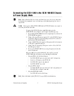
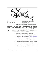
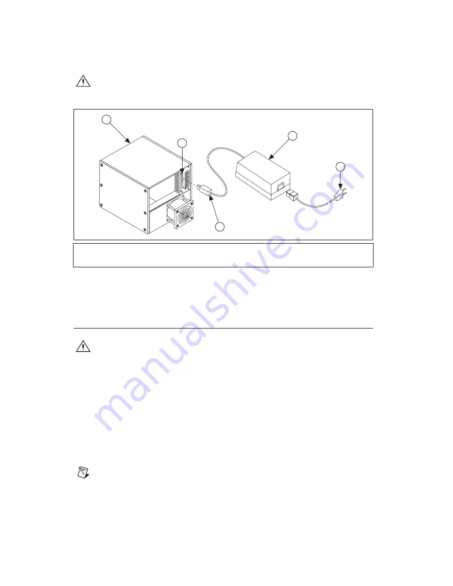
Figure 1.
Connecting the SCXI-1383 to the SCXI-1000DC Chassis
in Power Supply Mode
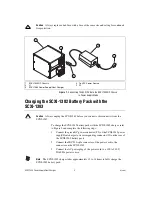
Charging the SCXI-1382 Battery Pack with the
SCXI-1383
Caution
Always unplug the SCXI-1383 before you connect or disconnect it from the
SCXI-1382.
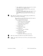
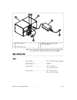
To charge the SCXI-1382 battery pack with the SCXI-1383 charger, refer
to Figure 2 and complete the following steps:
1.
Connect the green DC power connector (P2) of the SCXI-1383 power
supply/float charger to its corresponding connector (J2) on the rear of
the SCXI-1382 battery pack.
2.
Connect the IEC 320-style connector of the power cord to the
connector on the SCXI-1383.
3.
Connect the AC power plug of the power cord to a 100 to 240 V,
50/60 Hz power source.
Note
The SCXI-1383 charger takes approximately 12 to 14 hours to fully charge the
SCXI-1382 battery pack.
1
SCXI-1000DC Chassis
2
J1
3
SCXI-1383 Power Supply/Float Charger
4
To VAC Power Source
5
P2
1
2
3
4
5


