Chapter 2
Connecting the Signals
2-6
ni.com
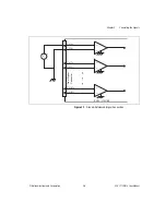
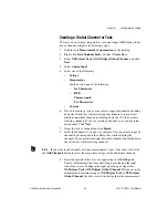
Figure 2-2.
Floating Signal Connection Referenced to Chassis Ground
Cold-Junction Sensor Connection
Pins A3 and A4 (CJ SENSOR) connect the temperature sensor located on
the SCXI-1300 or SCXI-1303 terminal blocks to the SCXI-1102/B/C
module. The CJ SENSOR signal is measured relative to CH GND. Pins A3
and A4 are connected within the SCXI-1102/B/C module so the position of
the
MTEMP
/
DTEMP
jumper on the SCXI-1300 or SCXI-1303 does
not
matter. The input is overvoltage-protected to 15 VDC with power on
and off.
Caution
Exceeding the overvoltage protection on the CJ SENSOR input can damage the
SCXI-1102/B/C module, the SCXIbus, and the DAQ device. NI is
not
liable for any
damages or injuries resulting from such signal connections.
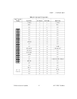
Rear Signal Connector
Table 2-3 shows the SCXI-1102/B/C module rear signal connector pin
assignments.
CH 31+
CH 31–
F
ront Signal
Connector
SCXI - 1102/B/C
CH 0+
CH 0–
CH 1+
CH 1–
V
s
+
–
+
–
+
–
+
–
CH GND
R
bias
Make This
Connection
to Ground
Reference
the Signal
Referenced to
Chassis Ground
Floating
Signal

