©
National Instruments Corporation
4-1
4
Theory of Operation
This section includes a brief overview and a detailed discussion of the
circuit features of the module.
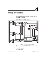
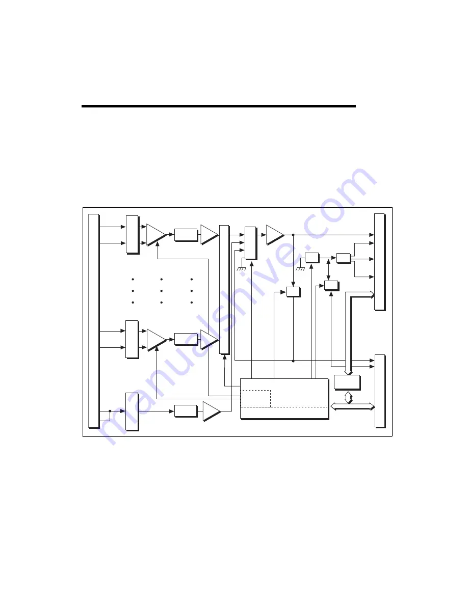
Refer to Figure 4-1 while reading this section.
Figure 4-1.
SCXI-1102/B/C Module Block Diagram
The major components of the SCXI-1102/B/C modules are as follows:
•
Rear signal connector
•
SCXIbus connector
•
SCXIbus interface
F
ront Signal Connector
CH 0 +
Gain 0
CH 0 –
CH 31+
CH 31–
Lowpass
Filter
Digital
Control
Calibration EEPROM
Lowpass
Filter
Lowpass
Filter
CJSENSOR
CH 0 +
Gain 31
Gain
Register
SCXIbus
Interface
SCXIb
us Connector
Rear Signal Connector
Switch
Mux
CH 0 –
AO GND
OUT REF
32-to-1 Mux
Switch
Inst.
Amp
+
Buffer
Switch
Mux
Input Protection
and Lo
wpass Filter
Inst.
Amp
+
Buffer
Buffer
AB 0 +
AB 0 –
–
–
Input Protection
and Lo
wpass Filter
Input Protection
and Lo
wpass Filter
Buffer


