18
|
ni.com
|
SLSC-12001 Chassis Getting Started Guide and Specifications
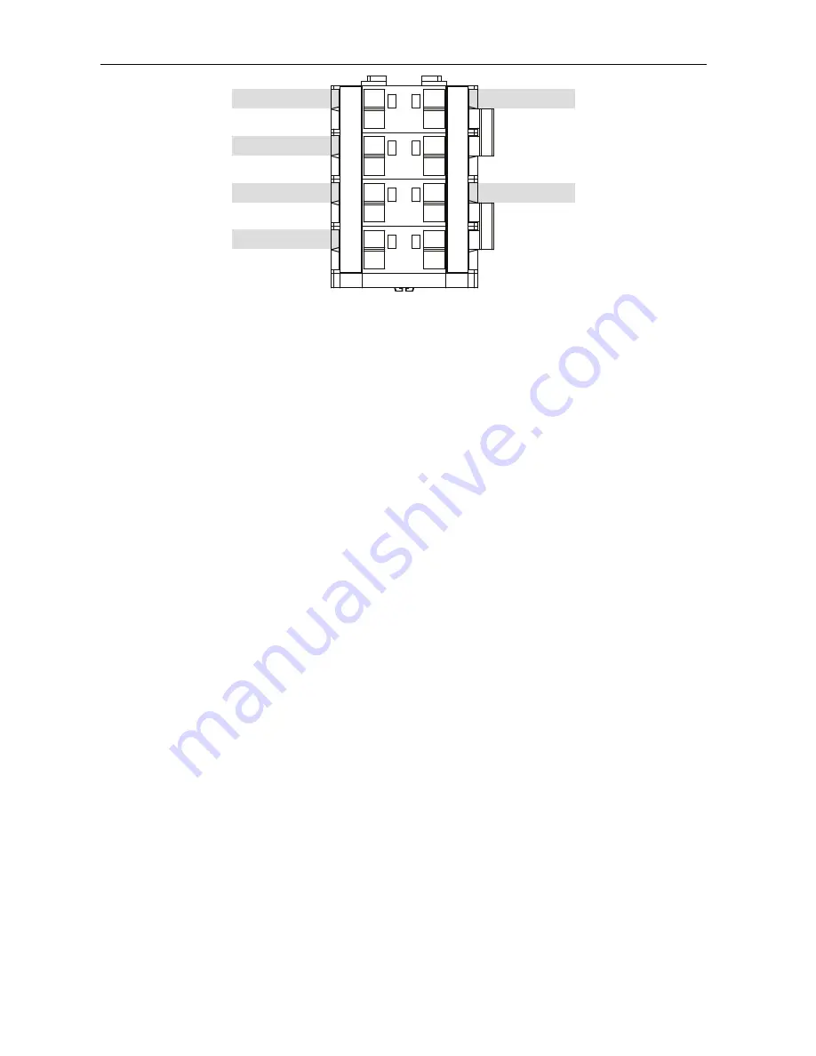
Figure 12.
Fan Terminal Block Wiring
Fan Installation
1.
Slide the fan(s) down onto the standoffs.
2.
Connect the fan wires to the terminal block as shown in Figure 12 using the process shown
in Figure 11.
a.
Insert the screwdriver into the spring clamp activation slot to open the corresponding
connector terminal.
b.
Press the new fan wire into the open connector terminal.
c.
Remove the screwdriver from the activation slot to clamp the wire into place.
d.
Repeat step a through c for each fan you install.
3.
Route the wires between the fans, not over them. For fan 3 in Figure 10, route the wire
beneath the fan tray and back through the two small grommets shown in Figure 13. Pull
the wire taut to prevent it from dangling loosely beneath the tray.
4.
Coil up the wires and cable as needed to prevent the wires from being pinched when the
panel is reattached. Use the chassis sheet metal cable tie anchors
shown in Figure 10, and
the plastic cable ties from the fan kit to hold the wires and cable tightly in place. Figure 14
illustrates the anchor and cable tie detail.
5.
Replace the top panel with the vent holes toward the back.
6.
Reinsert the two top panel retention screws using a Phillips screwdriver and tighten the
screws to a torque of 1.92 N · m (17 lb · in.).
7.
Replace the side panels.
F
a
n 5 Red (+)
F
a
n 5 Bl
a
ck (–)
F
a
n Pwr (–)
F
a
n Pwr (+)
F4+
F3+
F2+
F1+
F4–
F3–
F2–
F1–
F5+
J+
J+
V+
F5–
J–
J–
V–
F
a
n 4 Red (+)
F
a
n
3
Red (+)
F
a
n 2 Red (+)
F
a
n 1 Red (+)
F
a
n 4 Bl
a
ck (–)
F
a
n
3
Bl
a
ck (–)
F
a
n 2 Bl
a
ck (–)
F
a
n 1 Bl
a
ck (–)


