background image

NI TB-2666 Installation Instructions

4

ni.com

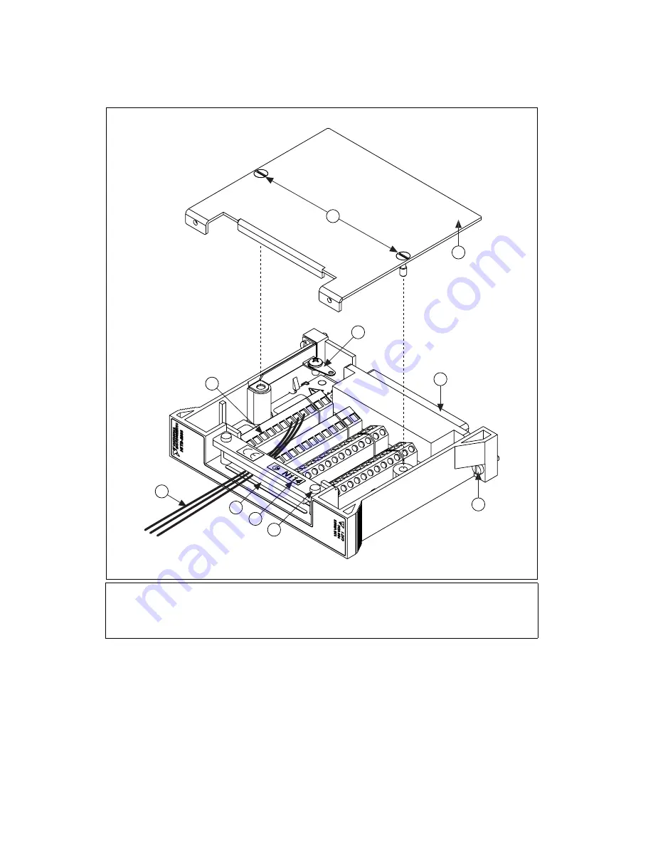
Figure 1.  

TB-2666 Terminal Block

1

Signal Wires

2

Strain-Relief Opening

3

Strain-Relief Bar

4

10-32 

×

 3/4 Inch Screw

5

Chassis Screws

6

Rear Connector

7

Terminal Block Top Cover

8

Top Cover Screws

9

Safety Ground Lug

10  Screw Terminals

9

2

3

7

6

5

4

1

8

10

Summary of Contents for TB-2666

Page 1: ... carry signal voltages no greater than 150 V This module can withstand up to 800 V impulse voltage Do not use this module for connection to signals or for measurements within Categories II III or IV Do not connect to MAINS supply circuits for example wall outlets of 115 or 230 VAC Refer to the NI Switches Getting Started Guide for more information on measurement categories When hazardous voltages ...

Page 2: ...r touch the exposed pins of connectors Ground yourself using a grounding strap or by touching a grounded object Touch the antistatic package to a metal part of the chassis before you remove the terminal block from the package Remove the terminal block from the package and inspect the terminal block for loose components or any sign of damage Notify NI if the terminal block appears damaged in any wa...

Page 3: ...lenty of space for the signal cables 5 Pull the signal cables at least one foot through the strain relief opening shown in Figure 1 6 Connect the safety earth ground to the safety ground lug 7 Connect the wires to the terminals by inserting the stripped end of the wire into the terminal Secure the connection by tightening the screw for each terminal When connecting the signals refer to the connect...

Page 4: ...ure 1 TB 2666 Terminal Block 1 Signal Wires 2 Strain Relief Opening 3 Strain Relief Bar 4 10 32 3 4 Inch Screw 5 Chassis Screws 6 Rear Connector 7 Terminal Block Top Cover 8 Top Cover Screws 9 Safety Ground Lug 10 Screw Terminals 9 2 3 7 6 5 4 1 8 10 ...

Page 5: ...ED 5 5 V MAX 3 3 V TRIGGERING CH 3 150 VDC 125 VRMS MAX 150 VDC 125 VRMS MAX GND IN GND OUT CH 2 CH 1 CH 0 CH 7 NO COM NC CH 6 NO COM NC CH 5 NO COM NC CH 4 NO COM NC NO COM NC NO COM NC NO COM NC NO COM NC CH 12 NC COM NO CH 13 NC COM NO CH 14 NC COM NO CH 15 NC COM NO CH 11 NC COM NO CH 8 NC COM NO CH 9 NC COM NO CH 10 NC COM NO NI PXI 2666 Screw Terminal Reference ...

Page 6: ... complete the following steps 1 Connect the PXI 2566 front connector to its mating connector on the terminal block 2 Tighten the top and bottom chassis screws on the back of the terminal block rear panel to hold it securely in place Figure 3 Installing the TB 2666 Terminal Block 1 Chassis Screw 2 PXI 2566 3 Front Connector 4 TB 2666 1 2 3 4 ...

Page 7: ...EN 55011 Class A at 10 m FCC Part 15A above 1 GHz Immunity EN 61326 1997 A2 2001 Table 1 EMC EMI CE C Tick and FCC Part 15 Class A Compliant Note For EMC compliance you must operate this device with shielded cabling CE Compliance This product meets the essential requirements of applicable European Directives as amended for CE marking as follows Low Voltage Directive safety 73 23 EEC Electromagneti...

Page 8: ...nal Instruments trademarks Other product and company names mentioned herein are trademarks or trade names of their respective companies For patents covering National Instruments products refer to the appropriate location Help Patents in your software the patents txt file on your CD or ni com patents 2003 2007 National Instruments Corporation All rights reserved 373638B Nov07 ...

Reviews: