©
National Instruments Corporation
17
UMI Accessory User Guide — UMI-4A
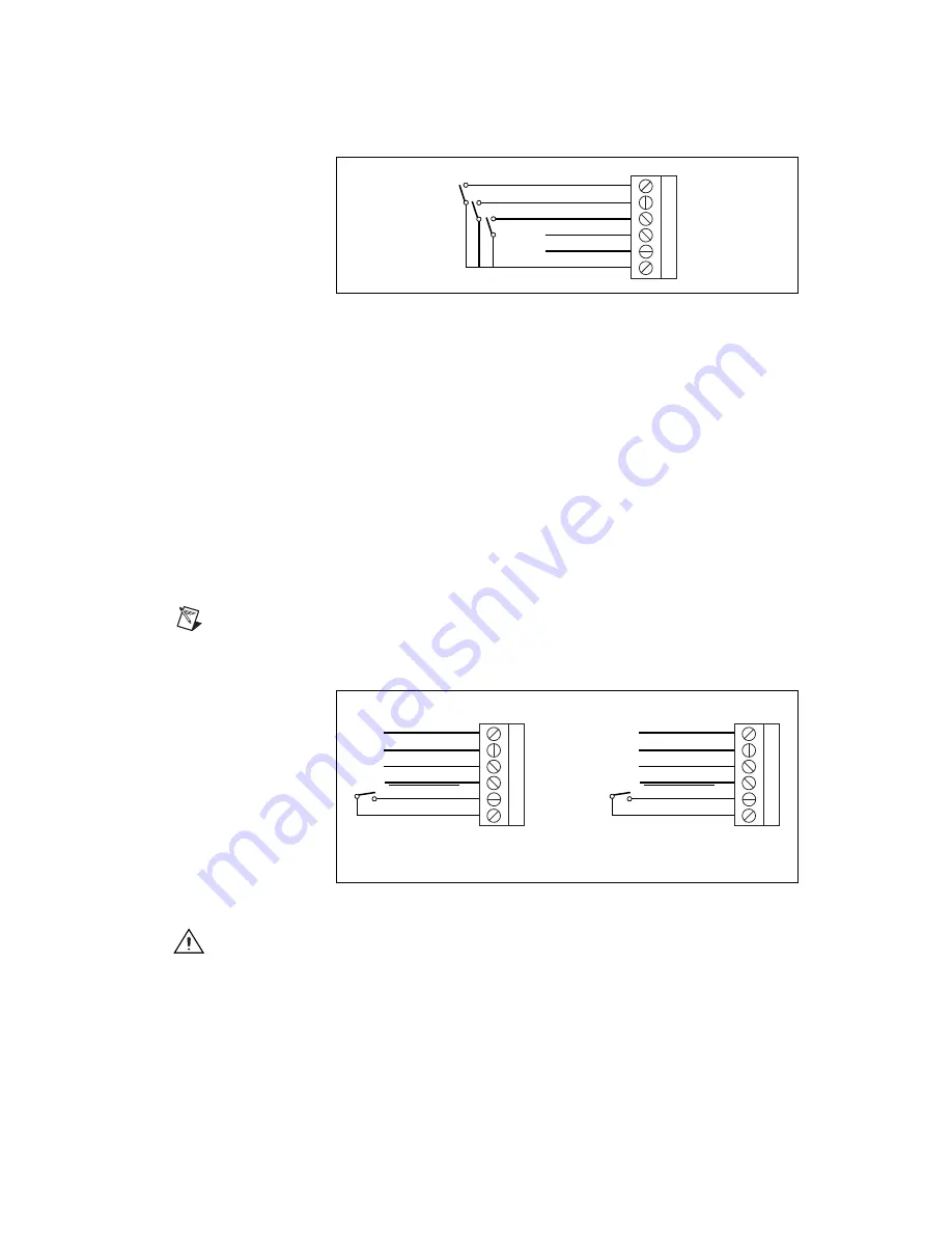
Figure 19.
UMI-4A Limit Switch Terminal Block Pin Assignment
(Passive Limit Switch Connection Example)
Digital I/O Terminal Blocks
The UMI-4A has two I/O connectors: a 34-pin male box header (J19),
which is compatible with standard Opto 22 I/O racks, and two 6-pin
removable screw terminal blocks (J10 and J11) for all other I/O
configurations. You can use both I/O configurations separately or in
parallel.
Pin 5 of each terminal block (J10 and J11) is an Enable Input connection.
This connection controls a system enable–system inhibit function. If your
configuration uses the inhibit output signal available on each per-axis
driver/amplifier terminal block, the enable input on J10 or J11 must be
connected to the common (ground) signal to enable the driver/amplifier.
Note
You do not need to duplicate the switch on both J10 and J11; use only one or the
other for the Enable Input.
Figure 20.
Using Available Pins On J10 and J11
Caution
If you connect the enable input to the common signal and bypass the
enable/disable function, you need to provide enable/disable control of the
drivers/amplifiers elsewhere in the system.
1
2
3
4
5
6
Forward Limit
Home Switch
Reverse Limit
Aux. VDC
+5 V (Output)
Digital Ground
1
2
3
4
5
6
I/O 1
I/O 2
I/O 3
I/O 4
Enable Input
Digital Ground
1
2
3
4
5
6
I/O 5
1
I/O 6
1
I/O 7
1
I/O 8
1
Enable Input
Digital Ground
or
J10
J11
1Reserved when used with a stepper board. Do not connect anything to these pins.
Summary of Contents for UMI-4A
Page 35: ......


