NI UMI-7774/72 User Guide and Specifications
8
ni.com
Caution
Do
not
touch exposed connector pins. Doing so may cause damage to the device.
3.
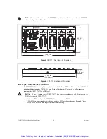
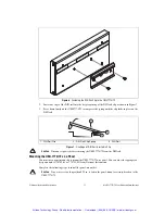
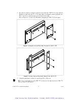
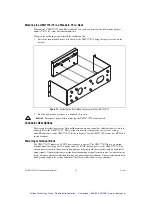
Mount the UMI-7774/72, if necessary. Refer to the
Mounting the UMI-7774/72
section for
mounting options.
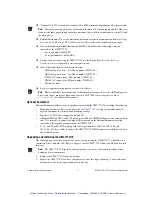
4.
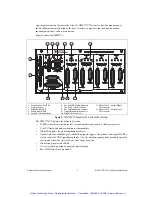
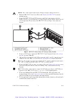
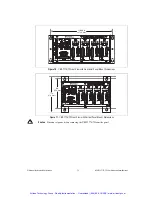
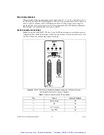
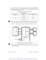
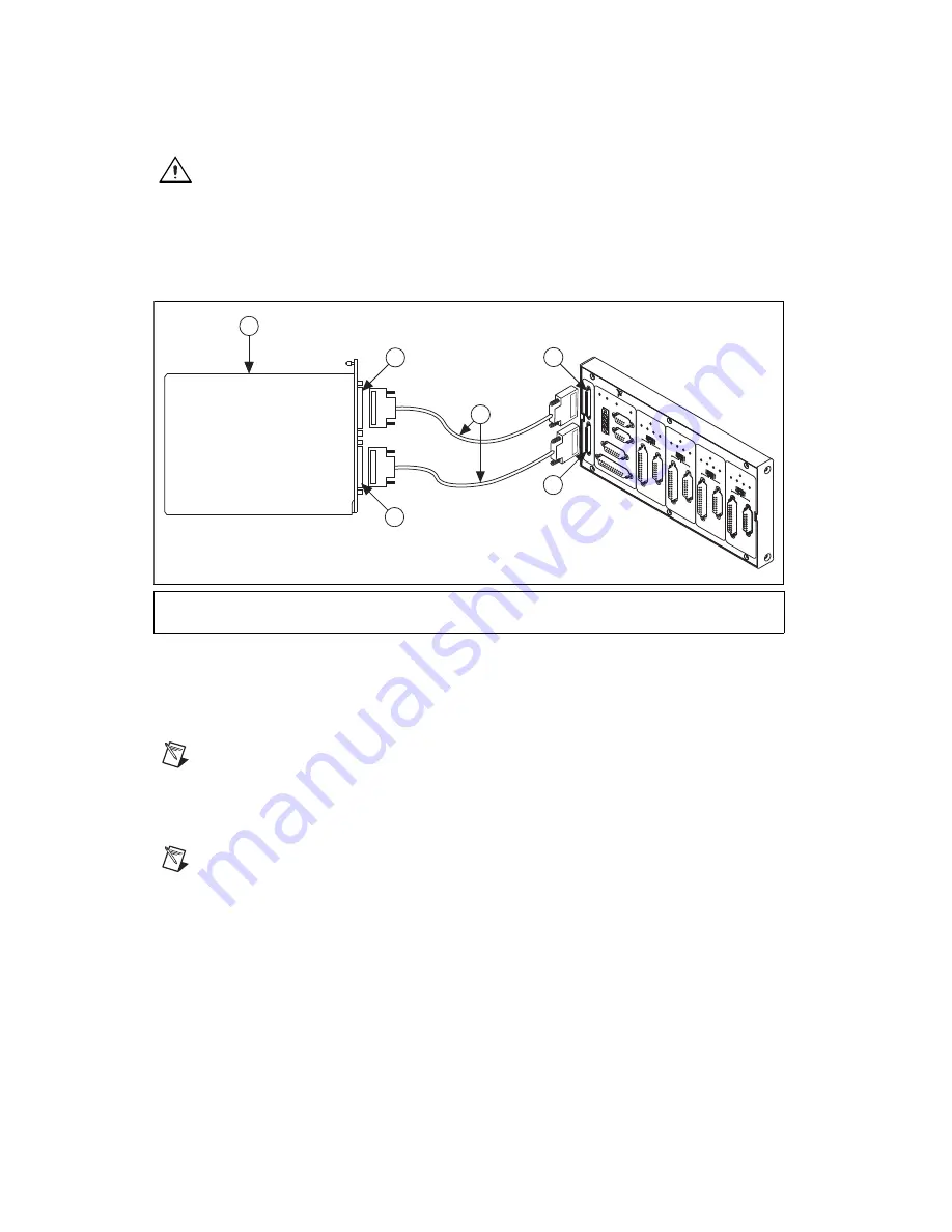
Connect the UMI-7774/72 to the NI 73xx motion controller by connecting one end of the
SHC68-C68-S cable to the 68-pin motion I/O connector on the motion controller and the other end
to the 68-pin motion I/O connector on the UMI-7774/72. Refer to Figure 2 for a connection
diagram.
Figure 2.
UMI-7774/72 Connected to an NI 73xx Series Motion Controller
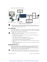
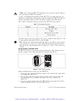
5.
Connect a 24 VDC power supply to the UMI-7774/72 V and C terminals. Refer to
Power Status
Indicators
for more information.
6.
(Optional) Connect a separate 5 to 30 VDC power supply to the V
iso
and C
iso
terminals to use the
isolation feature of the UMI-7774/72. Refer to
Power Status Indicators
for more information.
Note
If you do not connect a separate power supply to the V
iso
and C
iso
terminals you must connect
the V and V
iso
terminal together and connect the C and C
iso
terminal together.
7.
Connect the UMI-7774/72 to a stepper or servo drive. Refer to the
Connector Descriptions
section
for detailed information about the connectors including voltage considerations and wiring
diagrams.
Note
NI offers direct connect cables to connect the AKD analog servo drives or the P7000 series
stepper drives to the UMI-7774/72. Go to
ni.com/motion
for all available products.
8.
Connect any additional I/O to the UMI-7774/72 including limits, DIO, trigger inputs, and
breakpoint outputs. Refer to the
Connector Descriptions
section for detailed information about the
connectors including voltage considerations and wiring diagrams.
9.
Test the signal connections starting with the limit and home switches, then the encoders, and finally
the inhibit and command connections.
1
NI 73xx Series Motion Controller
2
NI 73xx Motion I/O Connector
3
UMI-7774/72 Motion I/O Connector
4
UMI-7774/72 Digital I/O Connector
5
SHC68-C68-S Cable
6
NI 73xx Digital I/O Connector
PO
WER
GLOB
AL ST
OP
GLOB
AL ST
OP
ANALOG INPUT
PO
WER
28VDC MAX
TRIGGER/BREAKPOINT
DIGIT
AL I/O
CONTR
OLLER
DIGIT
AL I/O
MO
TION I/O
V
Viso
INHIBIT ALL
INTERLOCK
AXIS 1
DISABLED
FAUL
T
FWD
HOME
REV
ACTIVE
LO
W
ACTIVE
HIGH
CONTR
OL
FEEDB
ACK
AXIS 2
DISABLED
FA
ULT
FWD
HOME
REV
ACTIVE
LO
W
ACTIVE
HIGH
CONTR
OL
FEEDB
ACK
AXIS 3
DISABLED
FA
ULT
FWD
HOME
REV
ACTIVE
LO
W
ACTIVE
HIGH
CONTR
OL
FEEDB
ACK
AXIS 4
DISABLED
FA
ULT
FWD
HOME
REV
ACTIVE
LO
W
ACTIVE
HIGH
CONTR
OL
FEEDB
ACK
NI UMI-7774 UNIVERSAL MO
TION INTERF
ACE
V
24VDC ±10%
C
Viso
(5–30VDC)
Ciso
NA
TIO
NAL
INST
RUM
ENTS
1
2
3
6
4
5
LIMIT LED
FA
ULT
ENABLE
LIMIT LED
FA
ULT
ENABLE
LIMIT LED
FA
UL
T
ENABLE
LIMIT LED
FA
UL
T
ENABLE
Artisan Technology Group - Quality Instrumentation ... Guaranteed | (888) 88-SOURCE | www.artisantg.com


